MHC-V5
4
SECTION 1
SERVICING NOTES
UNLEADED SOLDER
Boards requiring use of unleaded solder are printed with the lead-
free mark (LF) indicating the solder contains no lead.
(Caution: Some printed circuit boards may not come printed with
the lead free mark due to their particular size)
: LEAD FREE MARK
Unleaded solder has the following characteristics.
• Unleaded solder melts at a temperature about 40 °C higher
than ordinary solder.
Ordinary soldering irons can be used but the iron tip has to be
applied to the solder joint for a slightly longer time.
Soldering irons using a temperature regulator should be set to
about 350 °C.
Caution: The printed pattern (copper foil) may peel away if
the heated tip is applied for too long, so be careful!
• Strong viscosity
Unleaded solder is more viscous (sticky, less prone to fl ow)
than ordinary solder so use caution not to let solder bridges
occur such as on IC pins, etc.
• Usable with ordinary solder
It is best to use only unleaded solder but unleaded solder may
also be added to ordinary solder.
NOTES ON HANDLING THE OPTICAL PICK-UP
BLOCK OR BASE UNIT
The laser diode in the optical pick-up block may suffer electro-
static break-down because of the potential difference generated by
the charged electrostatic load, etc. on clothing and the human body.
During repair, pay attention to electrostatic break-down and also
use the procedure in the printed matter which is included in the
repair parts.
The fl exible board is easily damaged and should be handled with
care.
NOTES ON LASER DIODE EMISSION CHECK
The laser beam on this model is concentrated so as to be focused
on the disc refl ective surface by the objective lens in the optical
pickup block. Therefore, when checking the laser diode emission,
observe from more than 30 cm away from the objective lens.
NOTE OF REPLACING THE MS-476 BOARD
When the MS-476 board is defective, exchange the CDM90 ASSY
(Ref. No. CDM1).
NOTE OF REPLACING THE IC001, IC002, IC105, IC106,
IC302 AND IC306 ON THE ARAGON BOARD
IC001, IC002, IC105, IC106, IC302 and IC306 on the ARAGON
board cannot exchange with single. When these parts are damaged,
exchange the complete mounted board.
NOTE OF PERFORMING THE OPERATION CHECK IN
THE STATE THAT HEAT SINK WAS REMOVED
When performing the operation check in the state that this unit was
disassembled, it is possible to perform the operation check in the
state that heat sink was removed. But don’t perform the operation
check in the long time, and perform the operation check in the
volume state as low as possible.
TEST DISCS
Use following TEST DISC (for CD) when this unit confi rms the
operation and checks it.
Part No. Description
3-702-101-01 DISC (YEDS-18), TEST
4-225-203-01 DISC (PATD-012), TEST
J-2501-307-A DISC (HLX-A1), TEST
RELEASING THE DISC TRAY LOCK
The disc tray lock function for the antitheft of sample disc in the
shop is equipped.
Releasing Procedure:
1. Press the [
?/1
] button to turn the power on.
2. Press the [FUNCTION] button to turn the CD function.
3. Press two buttons of the [x] and [ENTER] simultaneously for
fi ve seconds.
4. The message “UNLOCKED” is displayed on the fl uorescent
indicator tube and the disc tray is unlocked.
Note: When “LOCKED” is displayed, the disc tray lock is not released by
turning power on/off with the [
?/1
] button.
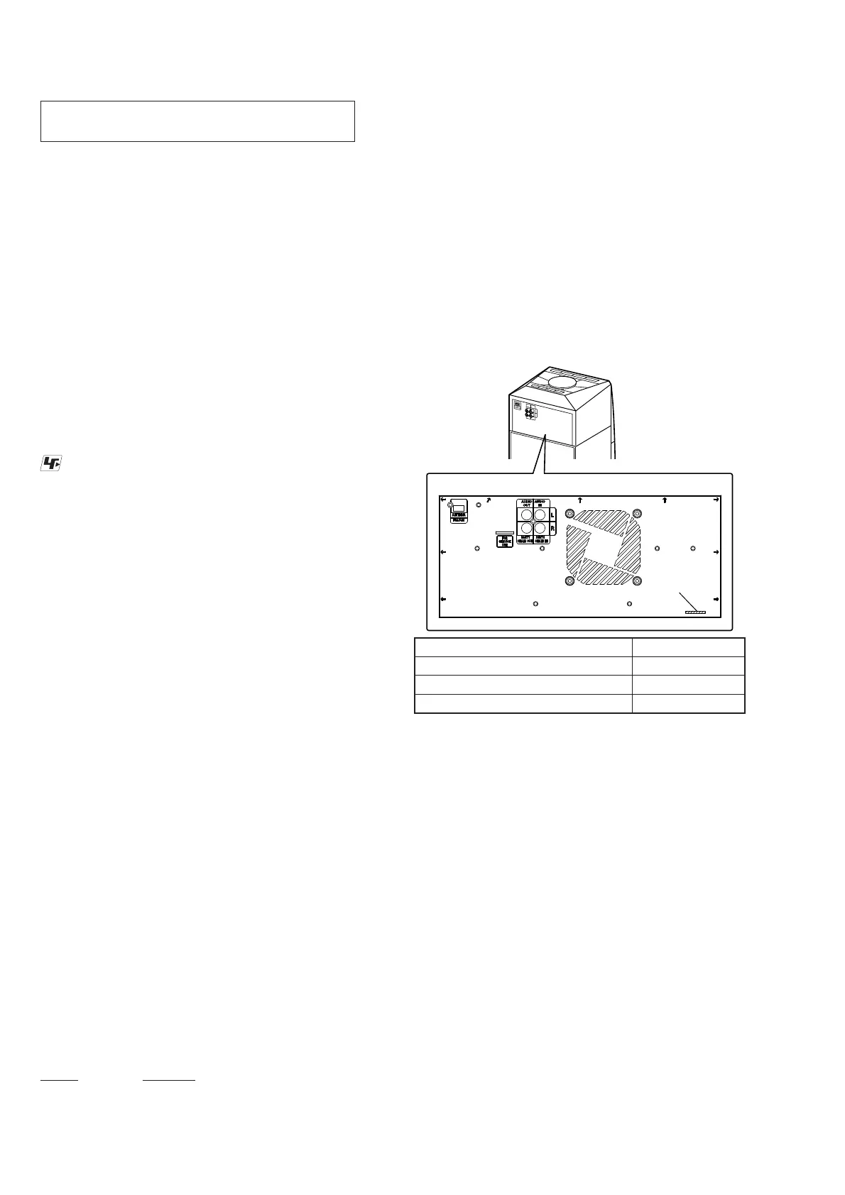
MODEL IDENTIFICATION
Distinguish by Part No. on the rear side of a main unit.
– Rear View –
– Back Panel –
PART No.
Model Part No.
120V AC Area in E model
4-484-682-0[]
US model
4-484-682-2[]
Chilean and Peruvian models
4-484-682-4[]

 Loading...