27
HCD-FX100W
DIAT SECTION
DIAT SIGNAL RF LEVEL ADJUSTMENT
This adjustment is performed in order to adjust the transmission
distance of RF signal for DIAT communication.
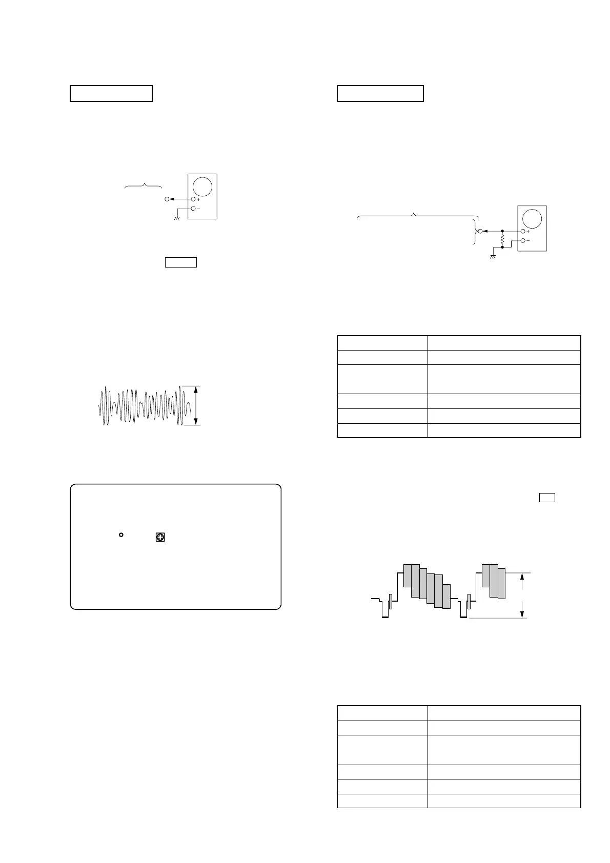
Connection:
Procedure:
1. Connect the oscilloscope to TP815 and GND on the TX board.
2. Connect DIR-T1 to DIR-T1 jack (I/O board: J602).
3. Adjust RV801 on the TX board so that the center of waveform
becomes 1.0 Vp-p.
4. Confirm trigger is locked.
5. Adjust RV801 on the TX board so that the center of waveform
becomes 2.2 to 2.4 Vp-p.
RF Signal Reference Waveform
SECTION 6
ELECTRICAL ADJUSTMENT
VOLT/DIV : 500 mV
TIME/DIV : 500 ns
level : 2.2 to 2.4 Vp-p
TP815
TX board
oscilloscope
– TX Board (SIDE A) –
TP815
RV801
Adjustment Location:
HDMI SECTION
ADJUSTMENT OF VIDEO SYSTEM
[TEST DISC LIST]
Use the following test disc on this mode.
• HLX-504 (NTSC Test Disc 504): J-6090-088-A
Connection:
1. Composite Level Adjustment (MIB01 Board)
<Purpose>
This adjustment is made to satisfy the standard, and if not adjusted
correctly, the brightness will be too large or small.
Mode Video level adjustment in test mode
Signal Color bar 100% (HLX-504 Track1)
Test point MONITOR OUT (VIDEO) connector
(75 Ω terminated)
Instrument Oscilloscope
Adjusting element RV501
Specification 1.0 Vp-p
Procedure:
1. Terminate the MONITOR OUT (VIDEO) connector in 75 Ω.
2. Connect an oscilloscope across 75 Ω terminator.
3. Turn the power on.
4. Set the test disc (HLX-504) on the tray and press
H button
to playback.
5. Confirm that oscilloscope waveform is clear and check
composite output level is correct or not.
6. If it is not correct, adjust the RV501 to attain 1.0 Vp-p.
MONITOR OUT (VIDEO)
COMPONENT VIDEO OUT (Y)
Set Back Panel
oscilloscope
75
Ω
1.0 Vp-p
2.Component Output Level Adjustment (MIB01 Board)
<Purpose>
This adjusts component output level. If it is incorrect, correct
brightness will not be attained when connected to, for instance,
projector.
Mode Video level adjustment in test mode
Signal Color bar 100% (HLX-504 Track1)
Test point COMPONENT VIDEO OUT (Y)
connector (75 Ω terminated)
Instrument Oscilloscope
Adjusting element RV502
Specification 1.0 Vp-p
 Loading...