28
HCD-C700/C900
SECTION 4
ELECTRICAL ADJUSTMENT
In making adjustment, refer to 5-2. Adjustment
Related Parts Arrangement.
Note: During diagnostic check, the characters and color bars can
be seen only with the NTSC monitor. Therefore, for
diagnostic check, use the monitor that supports both NTSC
and PAL modes
This section describes procedures and instructions necessary for
adjusting electrical circuits in this set.
Instruments required:
1) Color monitor TV
2) Oscilloscope 1 or 2 phenomena, band width over 100 MHz,
with delay mode
3) Frequency counter (over 8 digits)
4) Digital voltmeter
5) Standard commander
* RM-SS800 (1-418-838-11)
6) DVD reference disc
HLX-501 (J-6090-071-A) (dual layer)
HLX-503 (J-6090-069-A) (single layer)
HLX-504 (J-6090-088-A) (single layer)
HLX-505 (J-6090-089-A) (dual layer)
7) SACD reference disc
HLXA-509 (J-6090-090-A)
* Use only the designated remote control when adjusting this
system component.
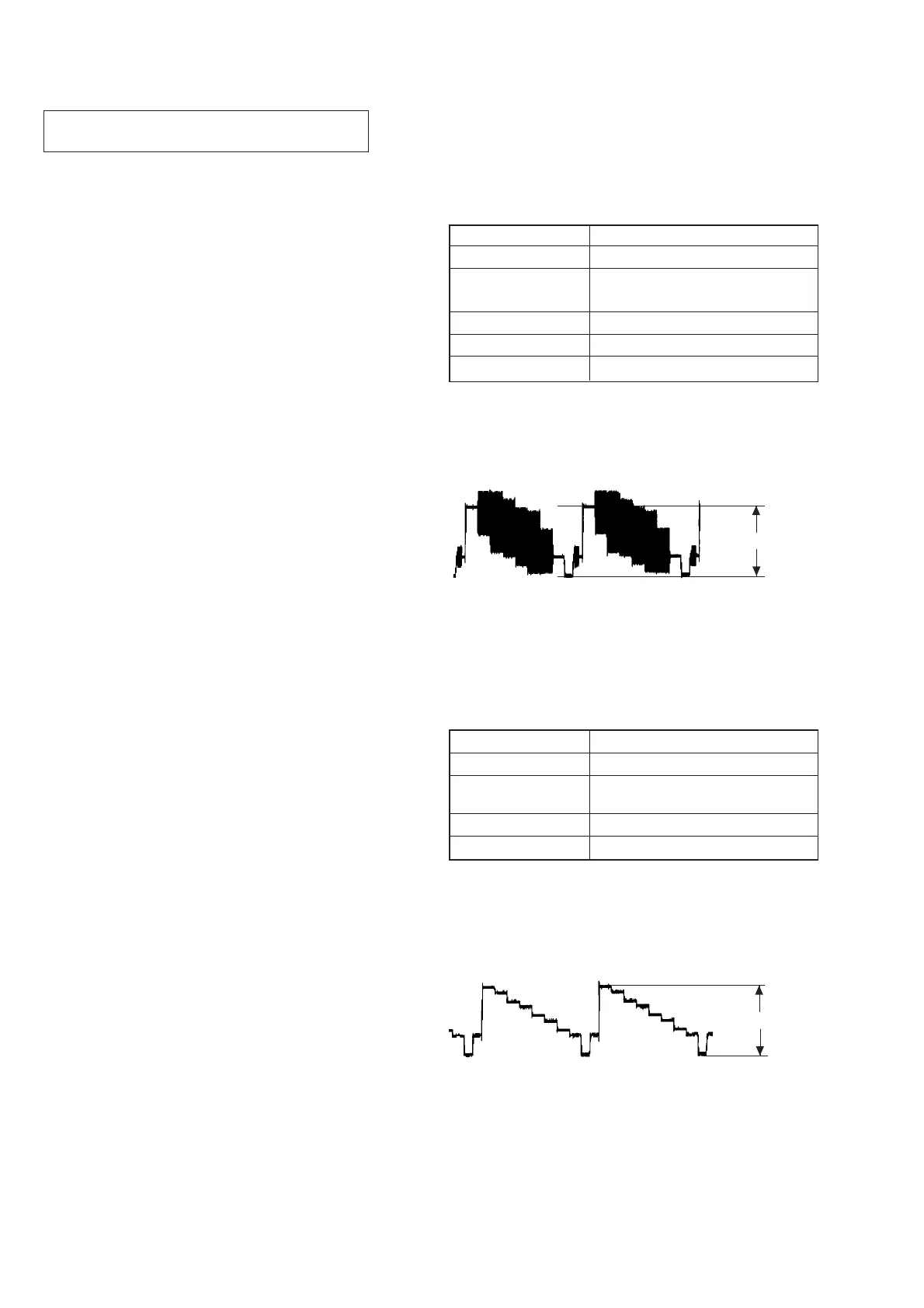
4-1. ADJUSTMENT OF VIDEO SYSTEM
1. Video Level Adjustment (DVD BOARD)
<Purpose>
This adjustment is made to satisfy the NTSC standard, and if not
adjusted correctly, the brightness will be too large or small.
Mode Video level adjustment in test mode
Signal Color bars
Test point
MONITOR OUT (VIDEO) connector
(75 Ω terminated)
Instrument Oscilloscope
Adjusting element RV501
Specification 1.0 ± 0.02 Vp-p
Adjusting method:
1) In the test mode initial menu “6” Video Level Adjustment, set
so that color bars are generated.
2) Adjust the RV501 to attain 1.0 ± 0.02 Vp-p.
Figure 5-1
2. S-terminal Output Check
<Purpose>
Check S-terminal video output. If it is incorrect, pictures will not
be displayed correctly in spite of connection to the TV with a S-
terminal cable.
Mode
Video level adjustment in test mode
Signal Color bars
Test point
S VIDEO OUT (S-Y) connector
(75 Ω terminated)
Instrument Oscilloscope
Specification 1.0 ± 0.1 Vp-p
Checking method:
1) In the test mode initial menu “6” Video Level Adjustment, set
so that color bars are generated.
2) Confirm that the S-Y level is 1.0 ± 0.1 Vp-p.
Figure 5-2
1.0 ± 0.02 Vp-p
1.0 ± 0.1 Vp-p
 Loading...