9|Page
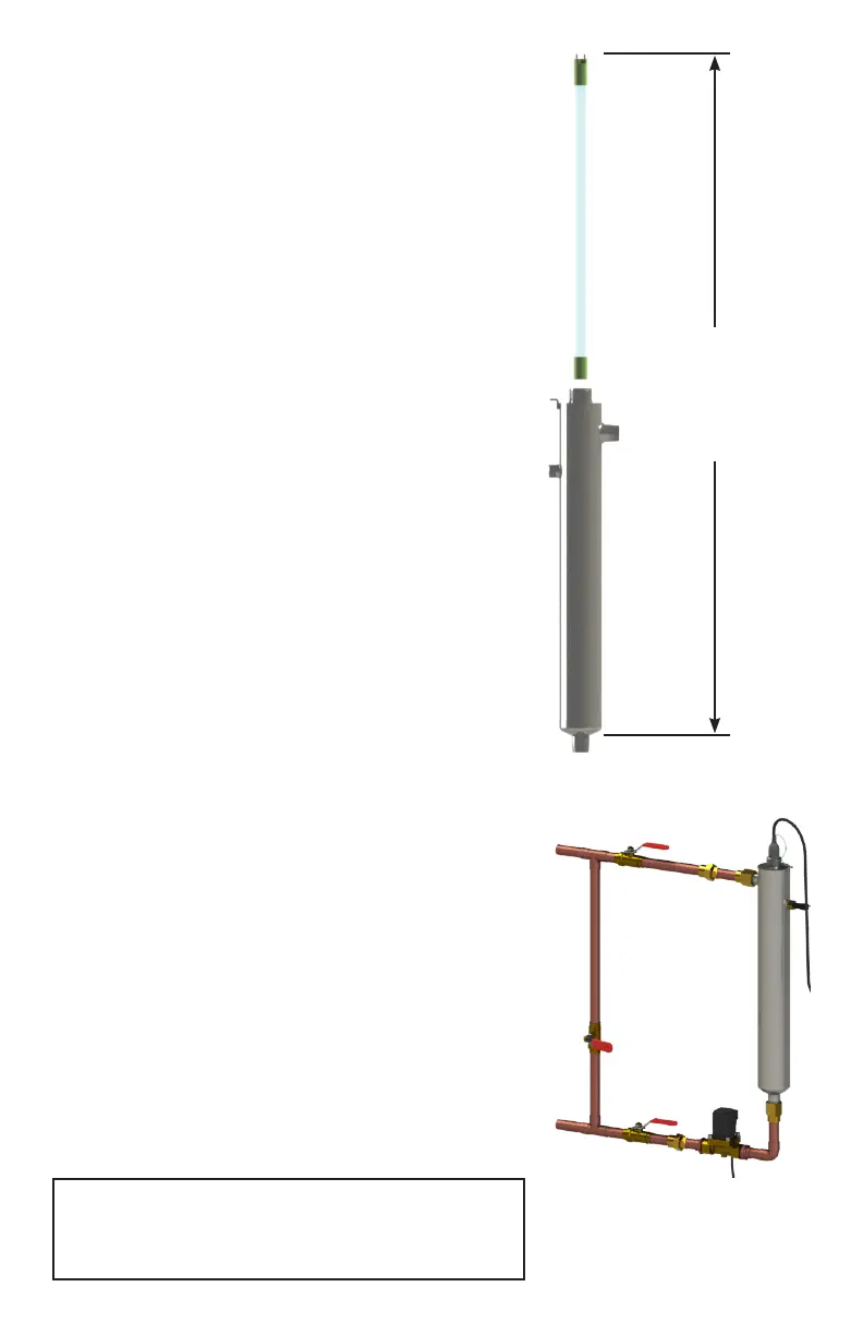
To facilitate lamp removal, ensure there is enough space at
the lamp connector end to safely remove the UV lamp and/
or quartz sleeve (See Figure 2). The controller will require
a ground fault circuit interrupter (GFCI or GFI) outlet and
should be mounted beside or above the reactor. PLEASE
NOTE: All UV disinfecon systems are intended for indoor
use only as they should not be exposed to the elements.
Installaon
Step 1: The reactor can be installed either horizontally or
vercally using the clamps provided. Vercal installaon is
the preferred method with the inlet at the boom (lamp
connecon at the top) as it allows any air that may be in the
lines to be easily purged from the system.
Step 2: The use of a by-pass assembly is recommended as
it will allow you to isolate the UV reactor. This will allow for
easier access in case maintenance is required (See Figure 3).
Step 3: Use the supplied fasteners to mount the UV
reactor to wood or drywall. If mounng to an alternate
material you will need to purchase the proper corresponding
fasteners.
Step 4: For water supplies where the maximum ow rate
is unknown, a ow restrictor is recommended so that the
rated ow of your parcular system is not exceeded. The
ow restrictor should be installed on the inlet port of the
reactor.
Step 5: It is recommended to have a licensed plumber
connect the UV reactor to the water supply and may be a
requirement depending on where you are located.
Step 6: Once the system has been plumbed in, gently
remove the quartz sleeve from its packaging being careful
not to touch the length with your hands. The use of coon
gloves is recommended for this procedure as oils from the
hands can leave residue on the sleeve and lamp which can
ulmately block the UV light from geng to the water.
Carefully slide the sleeve into the reactor unl you can feel
it hit the opposite end of the reactor. Align the sleeve so it
centered along the length of the reactor, then gently push it
in to lock it into the internal centering springs in the far side
of the reactor. CAUTION: Pushing too hard when the sleeve
is not aligned can damage the centering springs. Slide the o-
ring onto the sleeve unl it is bued up against the reactor.
Figure 2. Lamp
Removal Spacing
leave at least
an addional
reactor length
to facilitate
lamp and
sleeve removal
Note: Installaon of your disinfecon systems
shall comply with applicable provincial/state
& local regulaons.
Figure 3. By-pass
assembly
 Loading...