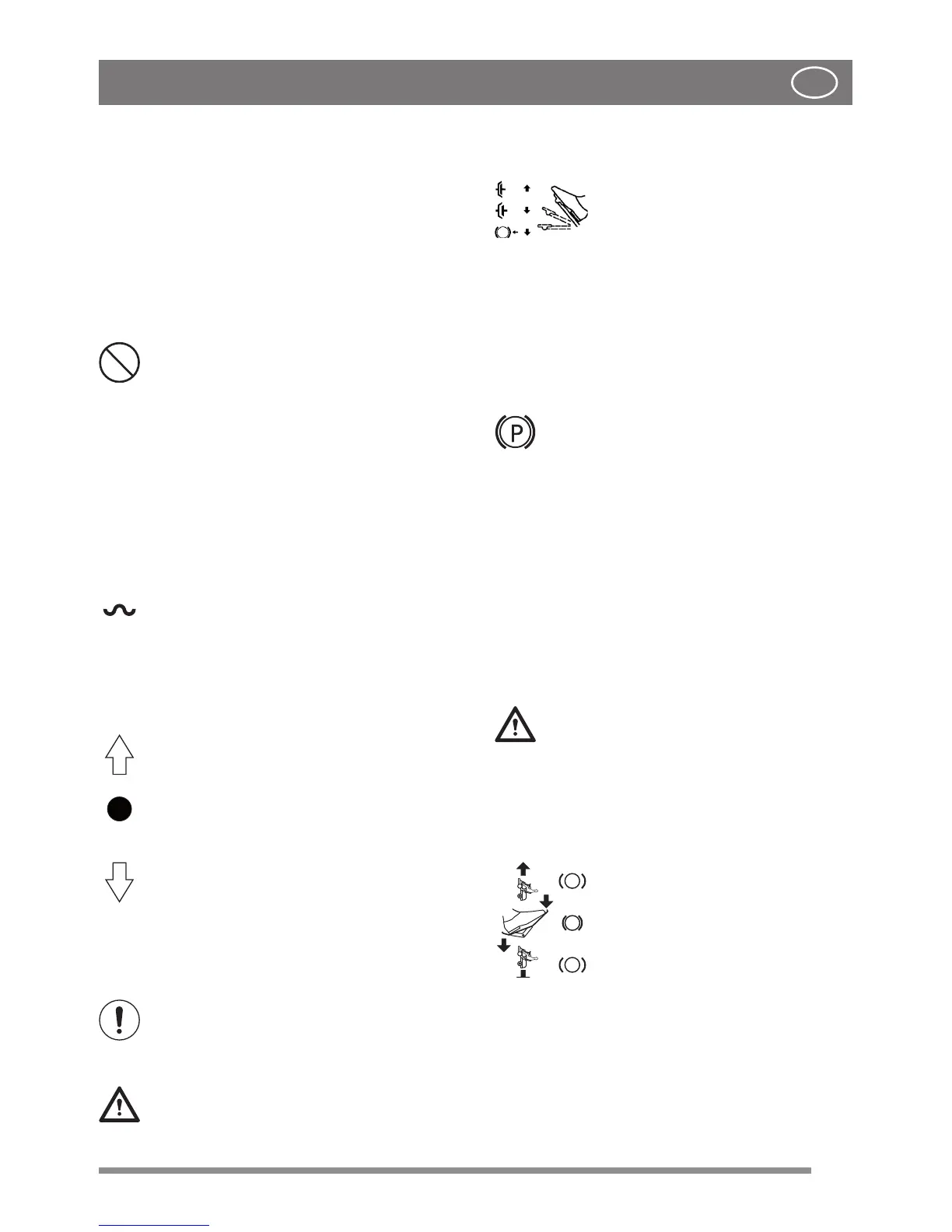
6.2 MECHANICAL ACCESSORY LIFT PE-
DAL [2WD] (12:C)
The control lever (12:C1)is used to take the
accessories from the operating position to the
transport position.
• Transport position: press the pedal right
down then lift your foot o: the pedal stays
down.
• Operating position: press and slowly release
the pedal.
Do not attempt to switch to the tran-
sport position while the hooked-up
accessory is in operation. This will de-
stroy the drive belt.
6.3 ACCESSORY LIFTING DEVICE,
HYDRAULIC [4WD] (14:H)
The hydraulic accessories lifting device is active
only when the engine is running and pedal (12:B)
is released. The accessories lifting device is con-
trolled by a lever (14:H).
The lever can be in one of the four following
positions:
Floating positions. Move the lever to the
most forward position, where it stops At this
point the accessory is lowered to the oa-
ting position. In this position, it is always re-
sting on the ground exerting the same pres-
sure and can follow the prole of the terrain.
Use the oating position when performing
work.
Lower position. The accessory is lowered.
Standby position (central). After lifting or
lowering, the lever returns to the standby
position. The accessory holds the position
of the last command executed.
Lift position. Move the lever to the furthest
back position until the accessory has rea-
ched the highest position (transport posi-
tion). Then release the lever: the accessory
remains blocked in the transport position.
6.4 PARKING BRAKE PEDAL (12:B)
Note: When the pedal is approxima-
tely at the halfway point of its stroke,
forward traction is disengaged and the
parking brake is deactivated.
Never partially press the pedal while
driving. There is a risk of overheating
the power transmission.
Il The pedal (12:B) has the following three posi-
tions:
Released: Traction is engaged. The
parking brake is not activated.
Pressed to halfway: Forward drive
disengaged. The parking brake is
not activated.
Pressed right down. Forward drive disengaged.
The parking brake is fully activated but not locked.
This position is also used as an emergency brake.
6.5 PARKING BRAKE LOCKING LEVER
(12:A)
The lever locks the “clutch-brake” pedal in
the pressed right down position. This fun-
ction is used to lock the machine on slopes,
during transport, etc., when the engine is
not running.
Locking:
1. Press the pedal (12:B) right down.
2. Move the locking lever (12:A) upward.
3. Release the pedal (12:B).
4. Release the locking lever (12:A).
Unlocking:
Press and release the pedal (12:B).
6.6 TRACTION PEDAL (12:F)
If the machine does not brake as ex-
pected when the pedal is released, use
the left pedal (12:A) as an emergency
brake.
The pedal determines the gearing ratio between
the engine and the drive wheels (= the speed).
When the pedal is released, the service brake is
activated.
- Press the pedal forward – the
machine moves forward.
- No load on the pedal – the ma-
chine is stationary.
- Press the pedal backward – the
machine reverses.
Reduce the pressure on the
pedal – the machine brakes.
A plate is installed on the upper section of the pe-
dal which can be adjusted to suit the driver’s foot.
 Loading...