Technical Information 40.2010 Page 27
TI_40_2010_13_01_02.fm
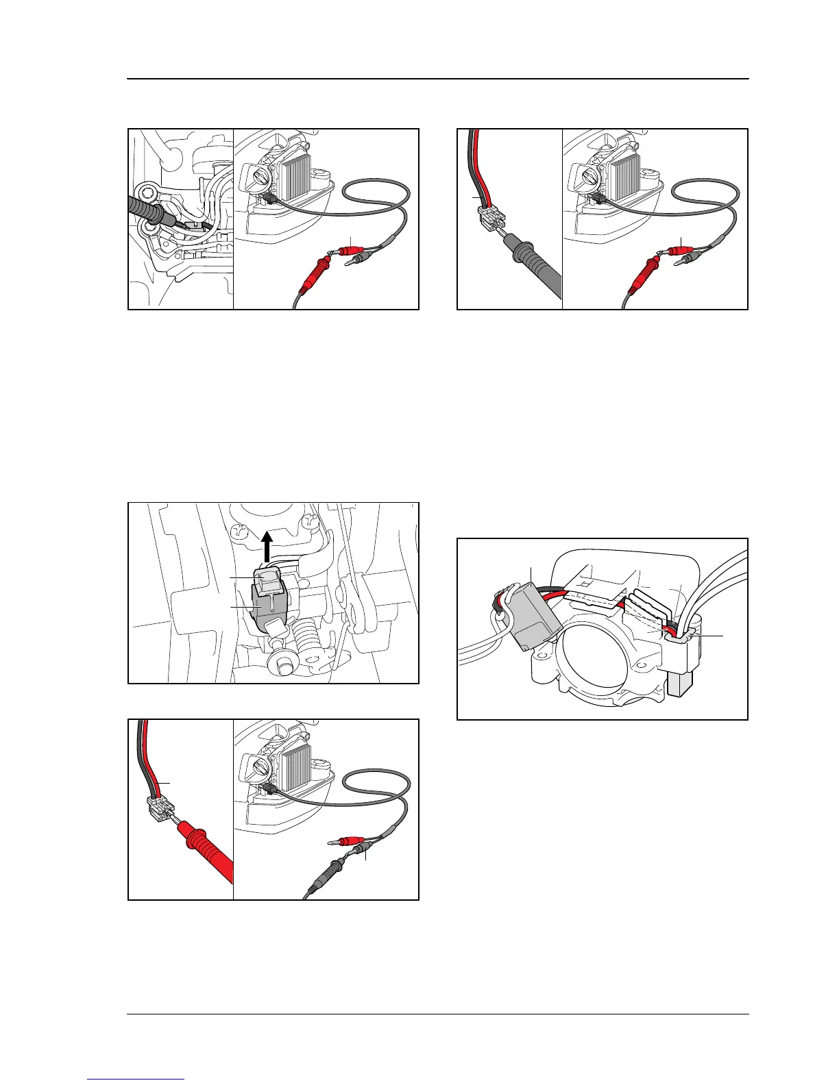
. Measure the resistance between black lead (3)
and red plug (4) of the diagnostic cable.
Target value: < 10 ohms
9.7.3 Checking leads between solenoid and
diagnostic jack
. Move choke lever to F
. Connect M-Tronic test lead 5910 840 0903 to
the diagnostic jack, see b 9.4
. Disconnect the plug (1) from the solenoid (2)
. Measure the resistance between red lead (3) at
the plug of the solenoid and black plug (4) of the
diagnostic cable.
Target value: < 10 ohms
. Measure the resistance between black lead (5)
at the plug of the solenoid and red plug (6) of the
diagnostic cable.
Target value: < 10 ohms
9.8 Cable routing
9.8.1 Cable routing at the bushing
Leads between diagnostic jack and switch gear
. Insert the thin black lead (1) between diagnostic
jack (2) and switch gear (3) in the guides
. Insert the thin red lead (4) between diagnostic
jack (2) and switch gear (3) in the guides
Make certain that in area (A) the leads (1, 4) are in
two separate guides and in area (B) the leads are in
the same guide – black lead (1) under the red
lead (4).
4
5903TI017 KN
3
1
5903TI013 KN
2
3
5903TI018 KN
4
6
5
5903TI019 KN
A
B
3
4
2
5903TI020 KN
1
 Loading...