Page 28 Technical Information 40.2010
TI_40_2010_13_01_02.fm
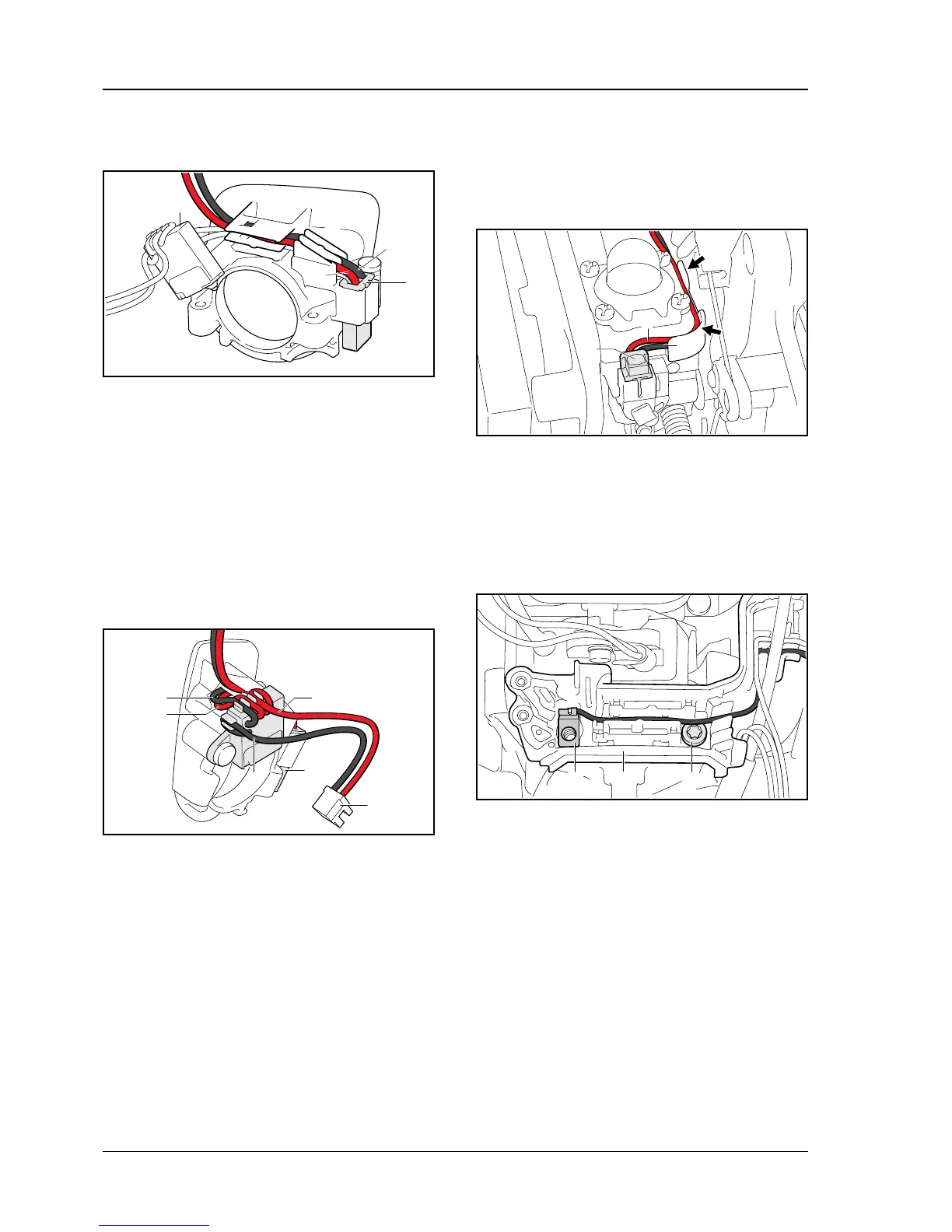
Leads between diagnostic jack and control unit
. Insert the thick black lead (5) between
diagnostic jack (2) and switch gear (3) in the
guides
. Insert the thick red lead (6) between diagnostic
jack (2) and switch gear (3) in the guides
Make certain that in area (A) the leads (5, 6) are in
two separate guides and in area (B) the leads are in
the same guide – black lead (5) under the red
lead (6).
9.8.2 Cable routing at the switch gear
. Insert the black lead (1) from the plug (2) of the
solenoid in the guide
. Insert the black lead (3) from the diagnostic
jack (4) in the guide
. Insert the red lead (5) from the diagnostic
jack (4) in the guide
. Insert the red lead (6) from the plug (2) of the
solenoid in the guide
9.8.3 Cable routing between switch gear and
solenoid
. Install bushing with switch gear – set choke
lever to position F
. Insert plug (1) at solenoid as far as it will go
. Insert black lead (2) and red lead (3) between
switch gear and solenoid in the guide – black
lead (2) under the red lead (3)
9.8.4 Cable routing in cable holder
. Fasten cable holder (1) to clutch housing with a
screw (2)
. Insert black lead (3) (switch gear) in the guide –
connector tag and terminal socket on the black
lead are welded and cannot be separated
3
B
2
5903TI021 KN
5
6
A
4
1
5903TI022 KN
2
3
5
6
3
1
5903TI023 KN
2
5903TI024 KN
1
2
3
 Loading...