
 Loading...
Do you have a question about the Stihl FS 460 C and is the answer not in the manual?
Details product variants with mowing handlebars, covering drive tube, gearbox, and harness.
Details product variants with sawing handlebars for forest use, covering drive tube and harness.
Explains the core function of the M-Tronic electronic engine management system.
Lists and briefly describes the individual components of the M-Tronic system.
Details the specific starting process managed by the M-Tronic system.
Describes how the M-Tronic system optimizes and controls engine acceleration.
Highlights the key benefits of the M-Tronic system, including easy starting and performance.
Provides step-by-step instructions for attaching the bicycle handle and support.
Identifies and describes the main controls and operating elements on the machine.
Instructions on the correct use of the choke lever for starting and warming up the engine.
Guides on adjusting the machine for optimal performance in summer and winter conditions.
Explains the pre-heat carburetor function for preventing icing in cold weather.
Instructions for operation in high temperatures and returning the shutter to summer position.
Details the components and use of the cover plate kit for extreme winter conditions.
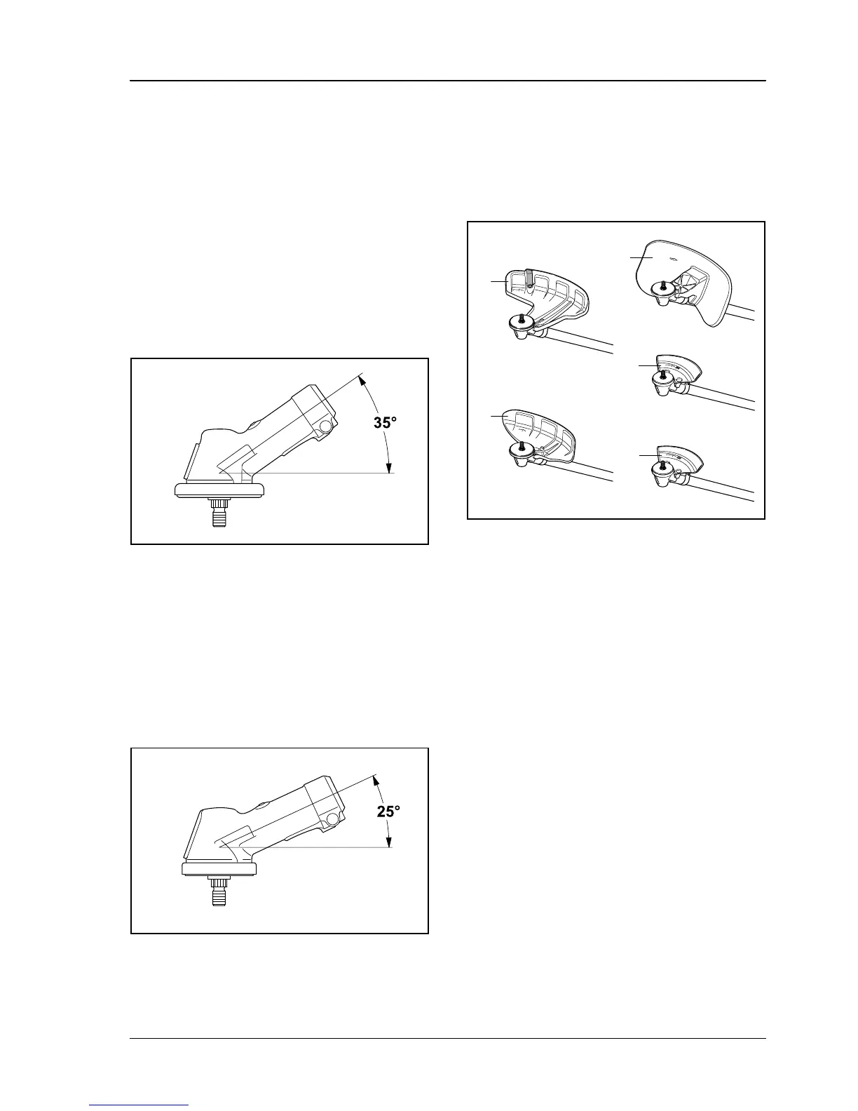
Describes the gearbox with a 35° gearhead angle for standard/long drive tubes.
Describes the gearbox with a 25° gearhead angle for short drive tubes.
Details deflectors and limit stops for standard/long drive tube versions.
Details limit stops specifically for the short drive tube version.
Explains the 4-point anti-vibration system for reduced vibration and improved control.
Highlights features and benefits of the Universal harness ADVANCE.
Highlights features and benefits of the Forestry harness ADVANCE.
Provides detailed technical specifications for the single cylinder two-stroke engine.
Details the fuel system, including mixture lubrication and fuel tank information.
Details the ignition module, speed limiter, and spark plug specifications.
Specifies variations in handle types, drive tube lengths, and antivibration systems.
Provides transmission ratios and gearhead angles for the gearbox variants.
Lists the dry weight and overall dimensions of the clearing saw.
Details cutting attachments for standard and long drive tube versions.
Lists various mowing heads and the specific deflector for them.
Lists grass cutting blades, brush knives, and their associated deflectors.
Lists circular saw blades and limit stops for standard/long drive tubes.
Details cutting attachments specifically for the short drive tube version.
Details new special tools for servicing and their respective applications.
Lists various aids, lubricants, and sealants used in servicing.
Introduces flow charts for diagnosing and troubleshooting M-Tronic system issues.
Flow chart for diagnosing and resolving issues when the engine fails to start.
Flow chart for troubleshooting engine start failures in position or flooding issues.
Flow chart to diagnose and resolve issues of low power or speed drops under load.
Flow chart for troubleshooting ignition system problems when no spark is present.
Flow chart for diagnosing and resolving issues when the engine stops unexpectedly.
Flow chart for diagnosing and resolving issues when the engine doesn't reach cut-off speed.
Guidelines for using an ohmmeter and ensuring reliable plug connections for testing.
Procedures for checking screwed and plug connections for proper electrical communication.
Steps to properly connect the M-Tronic test lead to the machine's diagnostic jack.
Procedure for measuring the resistance of the solenoid valve.
Overview of checks for the start detection system, including mechanical and electrical tests.
Instructions and procedures for checking the integrity of the wiring harness.
How to check the ground connection of the wiring harness at the control unit.
How to check the electrical leads connecting the control unit to the diagnostic jack.
How to check the electrical leads between the solenoid and the diagnostic jack.
Guidelines and best practices for routing cables to prevent damage and ensure reliability.
Specific instructions for routing cables at the switch gear assembly.
Specific instructions for routing cables between the switch gear and solenoid.
Important notes and precautions regarding service operations on the carburetor.
Procedure for accurately setting the flywheel air gap using a specialized gauge.
Steps for calibrating the control unit after replacement or servicing.
Indicates the location of the machine's serial number for identification.
Lists the estimated repair times for various service activities by qualified personnel.