23MS 311, MS 391
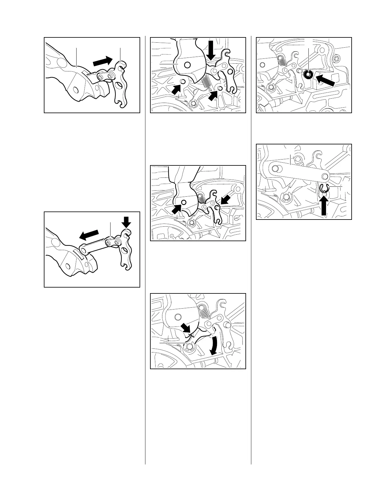
: Take the brake lever (2) out of the
hand guard (1).
– Inspect the pivot pins and replace
if necessary, b 5.5
– Inspect the cam lever and
replace if necessary, b 5.4
Installing
– Clean all disassembled parts,
b 14
: Hold the brake lever (1) so that
the brake spring attachment point
(arrow) is at the top.
: Push the brake lever (1) into the
hand guard recess and line up
the holes.
4903RA032 TG
1 2
4903RA033 TG
1
: Push the hand guard with brake
lever (1) over the machine until
they are positioned against the
pivot pins (arrows).
: Lift the bearing boss of the hand
guard and the brake lever a little
and position them over the pivot
pins (arrows).
: Turn the cam lever (1) to one side
until the cam of the hand
guard (arrow) slips passed it.
– Push the hand guard bearing
boss and the brake lever on to
the pivot pins.
4903RA034 TG
1
4903RA035 TG4903RA036 TG
1
: Fit the spacer sleeve (1).
– Fit the strap (1).
: Fit the E-clip (2).
4903RA272 TG
1
4903RA037 TG
1
2
 Loading...