45MS 311, MS 391
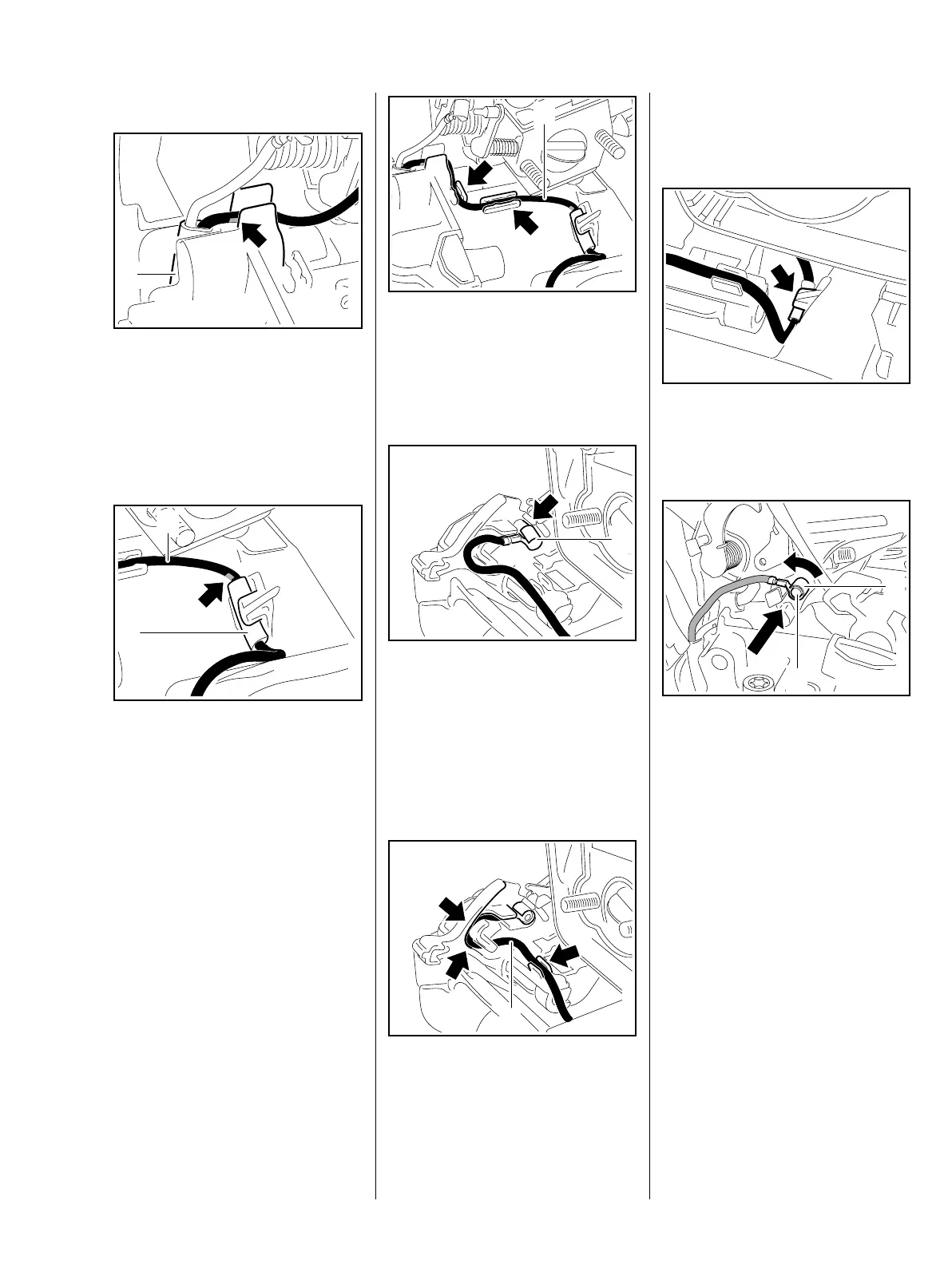
Installing
: Position the short circuit wire so
that the yellow mark lines up with
the edge (arrow).
– Push the wiring harness (1) into
the guide.
: Position the protective tube (2)
so that it is in line with the yellow
mark (arrow).
: Push the protective tube (2) with
short circuit wire (1) into the
guide (centered as shown).
4903RA104 TG
1
4903RA105 TG
1
2
The wire must be laid straight and fit
snugly against the housing.
: Push the short circuit wire (1) into
the guides (arrows).
– Install the filter base, b 12.3
– Position the ring terminal (1) so
that its crimped side faces up.
: Push the ring terminal (1) onto
the pin (arrow) as far as stop.
: Push the short circuit wire (1) into
the guides (arrows).
4903RA103 TG
1
4903RA107 TG
1
4903RA261 TG
1
Position the short circuit wire so that
it forms a loop and can move along
with the switch shaft.
: Check that short circuit wire is
properly seated, push it fully into
the guide (arrow) if necessary.
– Position the ring terminal (1) so
that its crimped side faces up.
: Fit the ring terminal (1) of the
ground wire on the pin (2) and
swing it down.
4903RA109 TG4903RA110 TG
2
1
 Loading...