25MS 311, MS 391
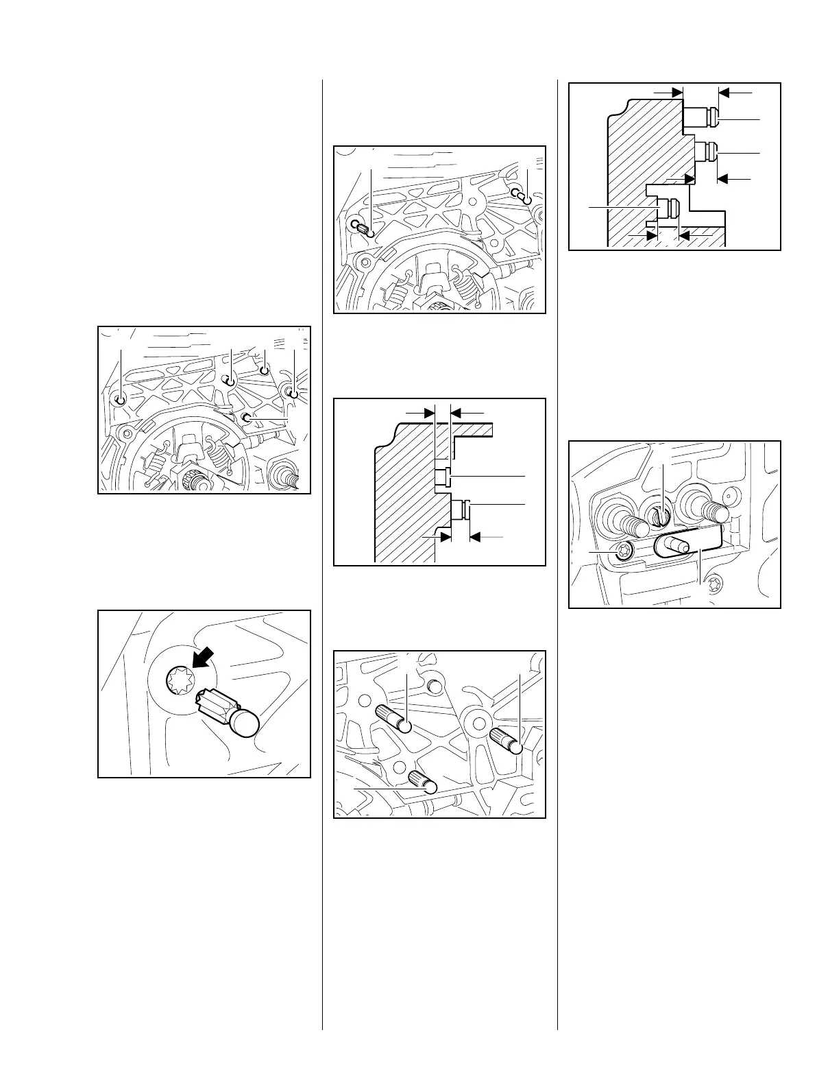
5.5 Pins
The anchor pins secure the springs.
Worn pins must be replaced – the
springs may otherwise become
detached and pop out.
The pins must be driven home
squarely.
For greater clarity, all parts have
been removed from the pins in the
following illustrations.
: Use suitable tool to remove the
pins (1 - 5).
Installing
– Before installing the new pin, coat
its knurled shank with
threadlocking adhesive, b 14
: Position the new pin in the
bore (arrow) so that the knurling
on the pin meshes with the
existing knurling in the bore.
4903RA044 TG
1
3
52
4
4903RA045 TG
Turn pin back and forth as
necessary.
: Drive home the pins (1 and 2) as
shown in the illustrations.
: Pin (1) a = about 2.9 - 3.3 mm
Pin (2) b = about 4.3 - 4.7 mm
: Drive home pins (3, 4 and 5) as
specified below.
4903RA046 TG
1
2
b
a
1
2
4903RA047 TG4903RA048 TG
3
5
4
: Pin (3) a = about 11.6 - 11.8 mm
Pin (4) b = about 4.6 - 4.8 mm
Pin (5) c = about 9.1 - 9.3 mm
5.6 Chain Tensioner
– Troubleshooting, b 3.2
: Turn the spur gear (2) clockwise
until the tensioner slide (1) butts
against the right-hand end and
the screw (3) is visible.
: Take out the screw (3).
a
c
b
4903RA049 TG
3
5
4
4903RA050 TG
2
1
3
 Loading...