16
Wiring requirements
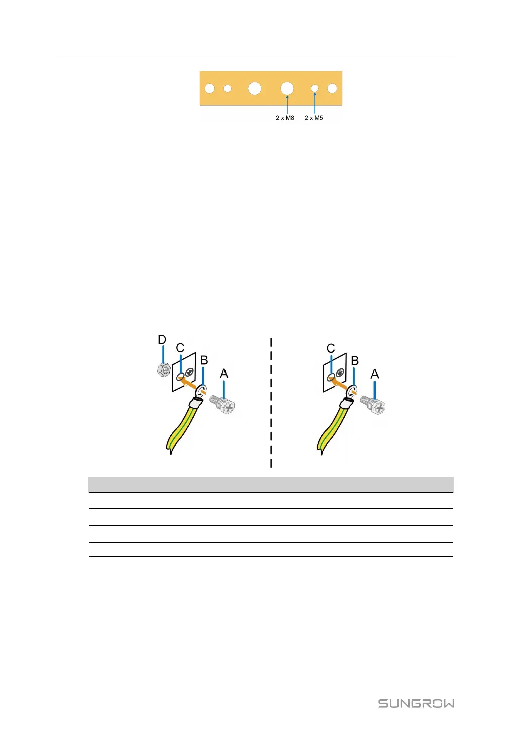
Unscrew the screws and nuts on the grounding holes and keep them properly for wiring.
6 mm
2
grounding cables are recommended.
Wiring steps
step 1 Draw the external grounding cable through the inlet hole at the bottom of the cabinet.
step 2 Strip off the protective layer and insulating layer of the grounding cable to expose the copper
core part, and select the appropriate DT/OT terminal for crimping. Refer to" Wiring Steps" .
step 3 Connect the grounding terminal into the grounding hole.
• When connecting to a M8 grounding hole, the recommended fixing method is as shown
in the following figure on the left, and the tightening torque is 18 ~ 23N.m.
• When connecting to a M5 grounding hole, the recommended fixing method is as shown
in the following figure on the right, and the tightening torque is 4 ~ 4.8N.m.
No. Name
A Screw assembly
B Grounding terminal
C Grounding hole
D Nut
- - End
5.3.2 Ethernet Port Connection
Brief introduction
Ethernet ports are reserved on both the firewall and the switch.
Wiring steps
step 1 Connect the Ethernet ports of switch to the controllers with CAT-5e cable.
5 Electrical Connection Installation Manual
 Loading...