23
AACC ppoowweerr ssuuppppllyy ppoorrtt aanndd PPLLCC ccoommmmuunniiccaattiioonn iinntteerrffaaccee
High voltages may be present on the AC power supply port "AC (100~277V)" and
communication interface "PLC(L1、L2)". Therefore, before cable connection, ensure
that the two ports are free of voltage and the grounding cable is reliably connected.
DDiiggiittaall iinnppuutt//oouuttppuutt ppoorrttss
Digital input/output ports (DIN and DO1~DO4) are configured to collect node data and
control node communication.
GGPPSS wwiirreelleessss aanntteennnnaa
The wireless antenna should be installed outdoors. The GPS antenna port (GPS/BDS)
are used for time synchronization and positioning.
• The time synchronization function is available to the Logger3000 itself only.
• Positioning function can be used to read out the geographic position of the
Logger3000 with the help of communication devices.
Ensure that the Logger3000 has been powered down before installing or removing the
GPS antenna.
RRSS448855 ccoommmmuunniiccaattiioonn ppoorrttss
For the RS485 communication ports (A1B1~A6B6), the communication distance should
be no more than 1,000m.
7.3 Overview
The Logger3000 can be connected to:
• devices in the PV system such as the inverter, combiner box, Meteo Station, and
energy meter through the RS485 port
• background devices through the Ethernet port
• transformer or other devices through the PLC port
7.4 Connecting to the Inverter
7.4.1 Connecting to the Device with RS485 Port
Use an RS485 shielded twisted pair (STP) to connect any RS485 port (A1B1–A6B6) of
the Logger3000 and the RS485 communication terminal of the inverter.
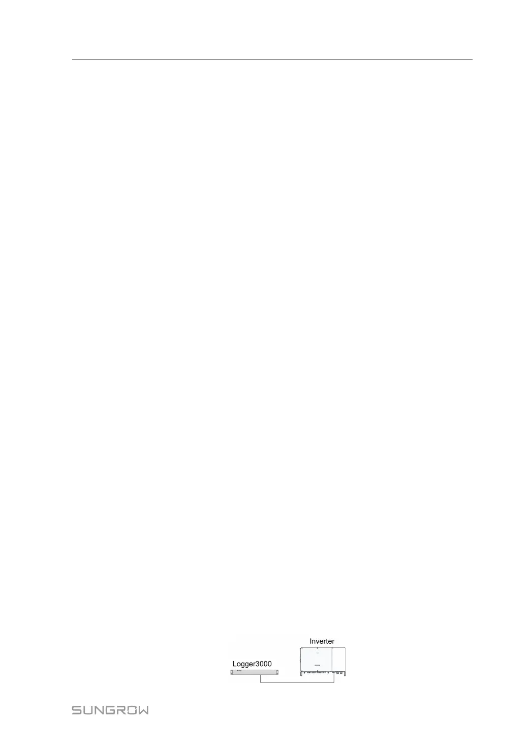
CCoonnnneeccttiinngg ttoo aa SSiinnggllee IInnvveerrtteerr
Insert the communication cable led from the inverter to any RS485 port (A1B1–A6B6)
of the Logger3000.
User Manual 7 Electrical Connection
 Loading...

