Electrical connection |
15
Connection
♦ Check if the data on the nameplate matches the
connection data.
♦ Complete the electrical connection according to the
circuit diagram.
♦ Fans with EC- motors must be switched on/off via the
control input.
♦ Use all of the locking screws.
♦ Connect the cable end in a dry environment.
♦ Insert the screws by hand to avoid damaging the
thread.
♦ Tighten all glands well in order to guarantee
protection class IP.
♦ Screw the lid of the terminal box/inspection switch
evenly tight.
♦ Install a circuit breaker in the permanent electrical
installation, with a contact opening of at least 3 mm
at each pole.
Protective grounding wire
The protective grounding must have a cross-section equal to or greater than that of the phase conductor.
Residual current circuit breaker
All-current-sensitive residual current circuit breakers are required for use in alternating-current systems with 50/60
Hz, in combination with electronic devices such as EC motors, frequency converters or uninterruptible power supplies
(UPS).
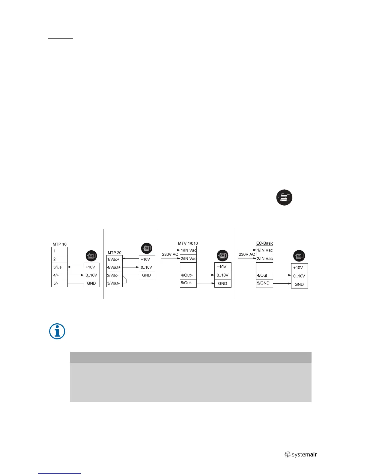
9.1 Electrical connection accessories
The following wiring diagrams show the electrical connections between accessories and
fans (with EC motor) or frequency converters (e.g. FRQ, FRQS, FXDM) which can be
controlled with a 0–10V signal. If you are not sure if your fan is equipped with an EC- motor
please see chapter 6 Name plate and type key, page 9.
motor/frequency
converter
In fans equipped with an EC motor, there is no additional motor protection needed. The motor protection is
integrated in the electronics of the motor.
Important
Damage to motor due to overcurrent, overload or short circiut.
♦ Lead-out temperature monitors must be integrated in the control circuit in such a way that, if a fault
occurs, the motor cannot switch on again automatically after it has cooled down.
♦ Motor lines and temperature monitor lines should be laid separately on principle.
♦ Without thermal protection: Use a motor protection switch!
| 005
 Loading...