Accessories
|
33
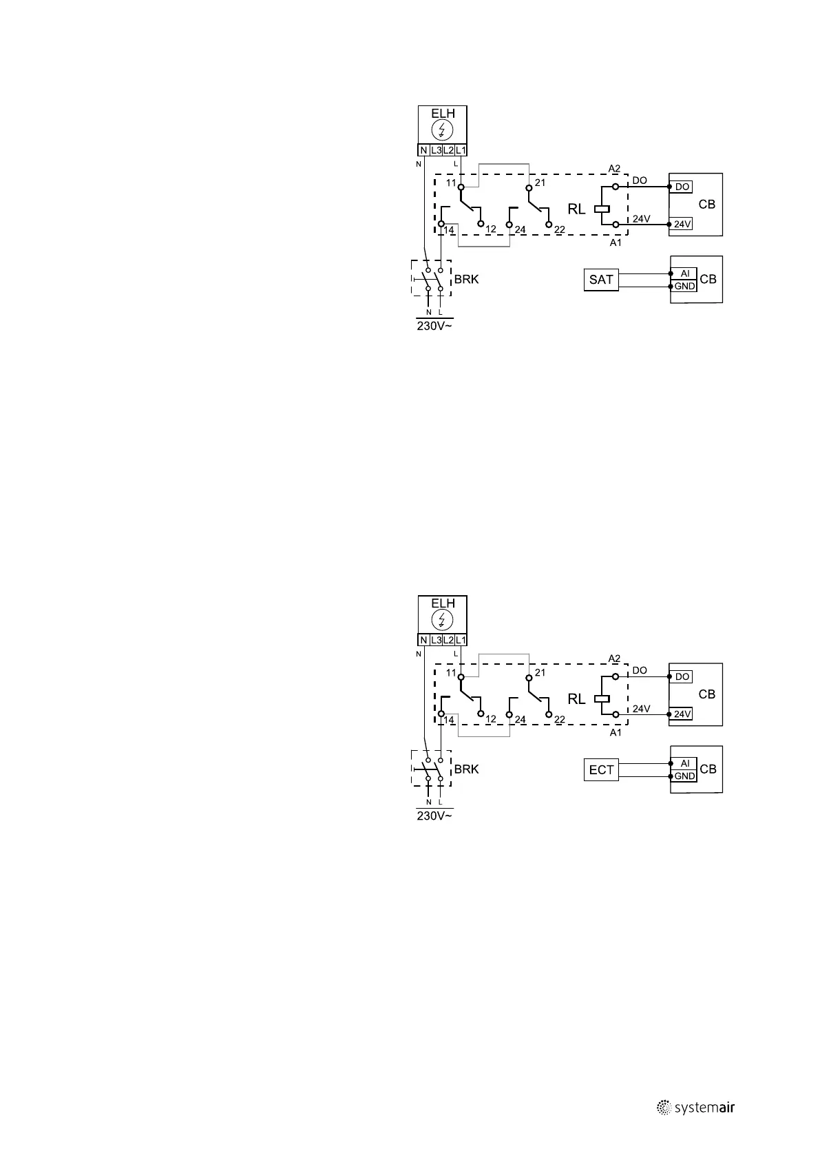
5.3.1.2 Heater installed in the supply air duct
Installation and connection
1. Install an electric heater (ELH) at least 100 mm distance
from the unit in the supply air duct. A relay (RL) is used
to control the heater. Connect relay to any free digital
output on the connection board (CB).
2. Connect the power supply to the electric heater via a
relay. A circuit breaker (BRK) is not included in the
package and must be ordered separately. It must be in-
stalled in the circuit.
3. Install a duct temperature sensor (SAT) after the elec-
tric heater and connect it to any free analog input on
the connection board (CB).
Supply air heater configuration
1. Go to Service menu
2. Enter password (default 1111)
3. Set the heater type: Components > Heater > Electrical.
4. Configure connection of the heater. Go to Service menu. Select Output menu. In next menu select DIGITAL tab.
Select the digital output to which the heater is connected. Example if it is connected to DO3 on the connection board,
then select DIGITAL OUTPUT 3 and select Step Controller Y1 Heating from the output type list.
5. Deactivate the internal supply air sensor: Service > Input > ANALOG > ANALOG INPUT 2 > Supply Air Temp.
Sensor (SAT) > Inactive Input.
6. After sensor configuration is changed, select the analog input to which the installed supply air temperature sensor
(SAT) is connected (for example AI5) and configure it as Supply Air Temp. Sensor (SAT).
5.3.1.3 Heater installed in the supply air duct (extra zone)
Installation and connection
1. Install an electric heater (ELH) at least 100 mm distance
from the unit in the supply air duct. A relay (RL) is used
to control the heater. Connect relay to any free digital
output on the connection board (CB).
2. Connect the power supply to the electric heater via a
relay. A circuit breaker (BRK) is not included in the
package and must be ordered separately. It must be in-
stalled in the circuit.
3. Install a temperature sensor (ECT) after the electric
heater and connect it to any free analog input on the
connection board (CB).
Supply air heater configuration
1. Go to Service menu
2. Enter password (default 1111)
3. Set the heater type: Components > Extra Controller > Extra Controller Mode > Heating.
4. Configure connection of the heater. Go to Service menu. Select Output menu. In next menu select DIGITAL tab.
Select the digital output to which the heater is connected. Example if it is connected to DO3 on the connection board,
then select DIGITAL OUTPUT 3 and select Step Controller Y4 Extra Controller from the output type list.
5. Configure the installed sensor. Go to menu Service > Input > ANALOG. Select the analog input to which the sensor
is connected. Example if it is connected to AI6 on the connection board, then select ANALOG INPUT 6 > Extra Con-
troller Temp. Sensor (ECT).
| v1
 Loading...