Accessories
|
35
4. Configure control signal to the actuator. Go to Service menu. Select Output menu. In next menu select ANALOG
tab. Select the analog output to which the control wire of the actuator is connected. Example if it is connected to AO3
on the connection board, then select ANALOG OUTPUT 3 and select Y1 Heating from the output type list.
5. Configure frost protection sensor (FPT). Go back to Input menu. Select ANALOG tab. Select the analog input to which
the frost protection sensor is connected. Example if it is connected to AI6 on the connection board, then select ANA-
LOG INPUT 6 and select Frost Protection Temperature Sensor (FPT) from the input type list.
6. Since a duct temperature sensor replaces internal supply air temperature sensor, it doesn’t need to be re-configured.
Note:
A duct temperature sensor can be connected to analog inputs 6–7 on the connection board for better
access and then configured as a supply air temperature sensor. However the internal supply air
temperature sensor must be disabled in the control panel first.
7. Water heater and its components are now configured.
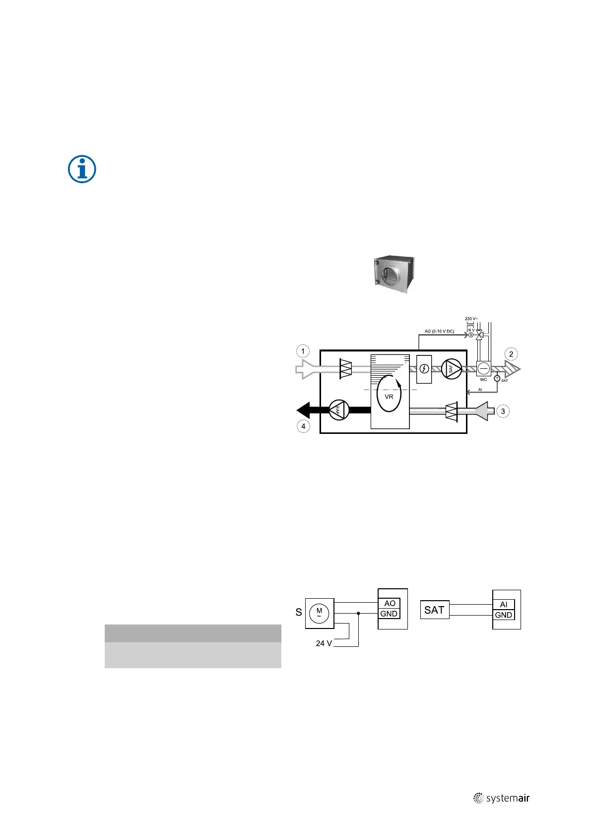
5.3.3 Duct water cooler
A duct water cooler is supposed to be installed in supply air duct to provide a
cooled down air to the apartment.
• WC — water cooling battery
• SAT — supply air temperature sensor
• S — valve actuator
• 1 — Outdoor air
• 2 — Supply air
• 3 — Extract air
• 4 — Exhaust air
Component/product — Article number:
• RVAZ4 24A Actuator 0-10V (S) — 9862
• Duct sensor -30-70C (SAT) — 211524
• Transformer 24V — 202692
VSR 300:
CWK 160-3-2,5 Duct cooler,circ — 30022
ZTV 15-0,4 2-way valve — 9829
ZTV 15-0,6 2-way valve — 6571
ZTR 15-0,4 valve 3-way — 9670
ZTR 15-0,6 valve 3-way — 6573
VSR 500:
CWK 200-3-2,5 Duct cooler,circ — 30023
ZTV 15-0,6 2-way valve — 6571
ZTV 15-1,0 2-way valve — 9823
ZTR 15-0,6 valve 3-way — 6573
ZTR 15-1,0 valve 3-way — 9672
Fig. 10 Duct cooler connections
Installation and connection
1. Install a duct water cooler in the duct. Connect pipes, 2/
3–way valve and actuator.
Important
Do NOT use 24V DC power output from the
connection board for valve actuator.
2. Connect actuator (S) to any free analog output.
3. An internal supply air temperature sensor (SAT, default connection AI2 on the main circuit board) must be replaced
by a duct temperature sensor which can be acquired as an accessory. A duct temperature sensor must be installed in
the duct after water cooler. Connect the duct temperature sensor to analog input 2 (AI2) replacing the internal supply
air temperature sensor.
| v1
 Loading...