62 Part C X2AM01 Radio Interface T2004 Multi-Control Head System Manual
© Tait Electronics Ltd May 2004
3 I/O Connections
This section describes the I/O connections on the board.
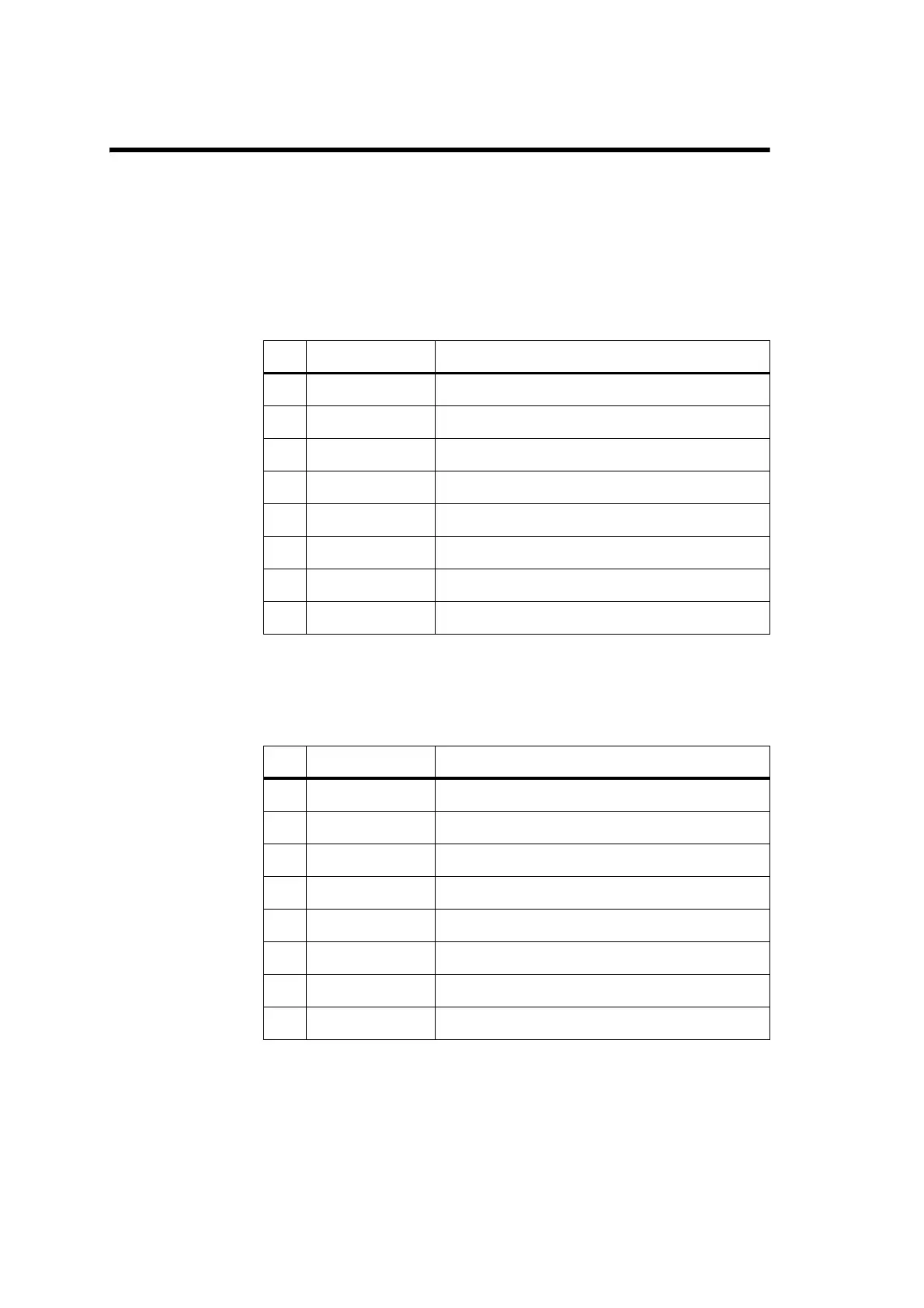
3.1 SK1: 8 Way Micromatch Socket to Radio
3.2 SK3: 8 Way Micromatch Socket to Control Heads
Pin Signal Description
1 +13.0V_UNSW Unswitched 13.8V from radio
2 GND Common ground
3 RX_DATA Data from heads to radio, 5V logic levels
4 TX_DATA Data from radio to heads, 5V logic levels
5 GND Common ground
6 AF Receiver audio, approx. -4dBm
7 MIC_IN Transmitter audio, approx. -30dBm
8 N/C Not connected
Pin Signal Description
1 DATA 2A Data from heads A
2 DATA 2B Data from heads B
3 PWR SW Remote power switch, Low=power on
4 Audio Balanced audio line
5 Audio Balanced audio line
6 GND Common ground
7 DATA 1A Data to heads A
8 DATA 1B Data to heads B
 Loading...