M850-00
T855 Circuit Operation
B2.7
Copyright TEL 31/09/98
2.7 Audio Processor
(Refer to the audio processor circuit diagram (sheet 2) in Section 6.3.)
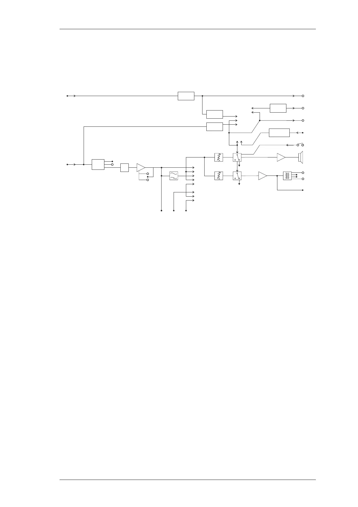
Figure 2.3 T855 Audio Processor Block Diagram
The recovered audio on pin 9 of IC310 is passed through a compensation network and
processed in a third order elliptic active filter to give the required response. Linking
(PL220 & PL210) is available to give either a flat or de-emphasised audio response, with
de-emphasis giving a -6dB/octave roll off. The output of IC210 is split to provide sepa-
rate paths for the speaker and line outputs. The "Audio 1", Audio 2" and "Speech" lines
allow access to the receiver’s audio path for external signalling purposes (refer to Sec-
tion 3.5).
The signals are passed to audio drive amplifiers IC240 and IC260. Under muted condi-
tions the inputs of these amplifiers are shunted to ground via transistors Q230 and Q290
respectively. The audio output of IC240 has a DC component which is removed by
C249, and this then drives a speaker directly. The output of IC260 is fed into a line trans-
former to provide a balanced 2-wire or 4-wire, 600 ohm output.
The speaker volume is set using the front panel "Monitor Volume" knob (RV205) and the
line level is set using the recessed "Line Level" potentiometer (RV210).
The red front panel "Gate" LED (D250) indicates the status of the mute circuit. When a
signal above the mute threshold is received, the LED is illuminated. The "Monitor
Mute" switch (SW201) on the front panel opens the mute, allowing continuous monitor-
ing of the audio signal (on = audio muted; off = audio unmuted).
The mute control line is available on pad 234 ("RX GATE OUT") for control of external
circuitry. A high (9V) on pad 234 indicates that the audio is disabled and a low (0V)
indicates that a signal above the mute threshold level is being received.
From
IF Stage
Demodulated
Signal
(*IF Audio
Compensation
Circuit)
Driver Amp
Line Output
12V
Relay
Speech
Audio 1
Output
Audio 2
Input
High Pass
Filter
Speaker
Mute
Line
Mute
Carrier
Mute
RSSI
(Optional)
Rx Disable
Timer
Noise
Mute
PL260
PL250
PL270
RSSI Output
Mute Relay
Gate Output
Rx Disable
(Optional Pad)
Mute Disable
Speaker Output
Line Monitor
12
1
2
2
1
3
1
5
2
2
3
3
4
1
PL240
PL230
Driver Amp
Flat/De-
emphasis
LPF
PL210
2
3
Flat/De-
emphasis
Amplifier
PL220
1
2
3
*IF
Comp
Monitor
Volume
Line
Level
 Loading...


