AccuLoad IV Installation & Maintenance Manual
Installation 26
3.5.4.3 A4M Special I/O Considerations
The DC digital output terminals on TBK5 can be configured as low-speed pulse outputs, as follows:
3.5.4.4 A4M S1 DIP Switch Settings
The following table provides information about S1 dual in-line package (DIP) switch settings on the A4M
board.
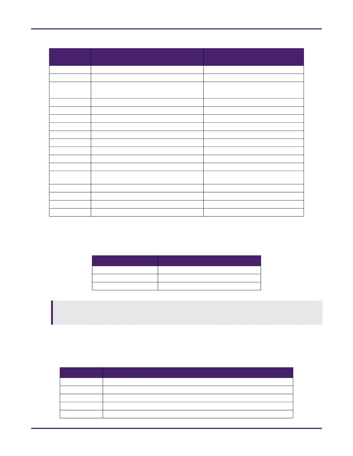
TBK4 DC digital input Digital inputs 1 through 3
TBK4 Pulse output Pulse output 1
TBK5 DC digital output Digital outputs 1 through 3
or pulse outputs 3 through 5
TBK5 Pulse output Pulse output 2
TBE1 AC power input (115 to 230) Not applicable
TBE2 AC digital input Digital inputs 7 through 11
TBE3 AC digital output Digital Outputs 4 through 9
TBE4 Serial communication port RS232 Comm 4
TBE4 DC digital input Digital inputs 4 through 6
TBE4 24 VDC power - 1 amp maximum Not applicable
TBE4 DC electronic ground Not applicable
TBE5 Analog I/O Analog I/O 1 through 6
TBE6 High-speed prover pulse output Not applicable
TBE6 Analog I/O Analog I/O 4 through 6
TBE7 AC digital input Digital outputs 10 through 14
PT 1 Meter pulse inputs Pulse inputs 1 through 6
PT 2 Meter pulse inputs Pulse Inputs 7 through 8
Table 8: Low-Speed Pulse Outputs
Terminals Outputs
Terminals 1 and 2 Digital output 1 or pulse output 3
Terminals 3 and 4 Digital output 2 or pulse output 4
Terminals 5 and 6 Digital output 3 or pulse output 5
If digital valve control is used for any product- or flow-controlled additive meters connected to pulse
inputs located on the A4M or A4B board, the digital outputs controlling the flow control valve must also
be located on the A4M or A4B, respectively.
Table 9: A4M S1 DIP Switch Settings
Switch Setting
S1-1 Factory use
S1-2 Factory use
S1-3 Reserved
S1-4 Reserved
S1-5 Reserved
Table 7: A4M I/O Index Numbering
Terminals Type of I/O
AccuLoad Configuration Index
Number

 Loading...


