AccuLoad IV Installation & Maintenance Manual
Installation 44
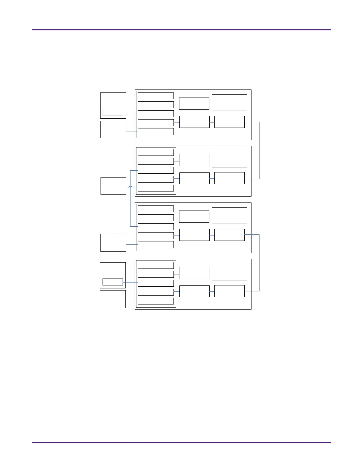
3.7.1.3 SA Model Ethernet Connections
Ethernet is used for communication between the SA model’s FCM and MMI units, as shown in the
following diagram. On each MMI’s THMI board, the Ethernet cable connects the ETH1 RJ45 jack to a
board set in the FCM.
3.7.1.4 SA Board Set IP Addresses
The addresses of the MMI’s board sets are assigned using DIP switches on each board in the set. The DIP
switches must be set based on the board set (A, B, C, or D) with which the board is associated, as detailed
in the table below. The A4M module has two DIP switches (SW1 and SW2) and the A4B and A4I boards
each have a single DIP switch (SW1). (See section x to find these DIP switches on each board’s layout).
Figure 41: Ethernet Connections for SA Model
External
Network
Connection
THMI
MMI A
Primary CPU
A4I (optional)
Board Set SAA
A4M
ETH1
ETH2
ETH3
ETH4
A4B
External
Network
Connection
Primary CPU
A4I (optional)
Board Set SAB
A4M
ETH1
ETH2
ETH3
ETH4
A4B
Primary CPU
A4I (optional)
Board Set SAC
A4M
ETH1
ETH2
ETH3
ETH4
A4B
External
Network
Connection
Primary CPU
A4I (optional)
Board Set SAD
A4M
ETH1
ETH2
ETH3
ETH4
A4B
External
Network
Connection
THMI
MMI B
(optional)

 Loading...


