English
7
S1
A
S2
S3
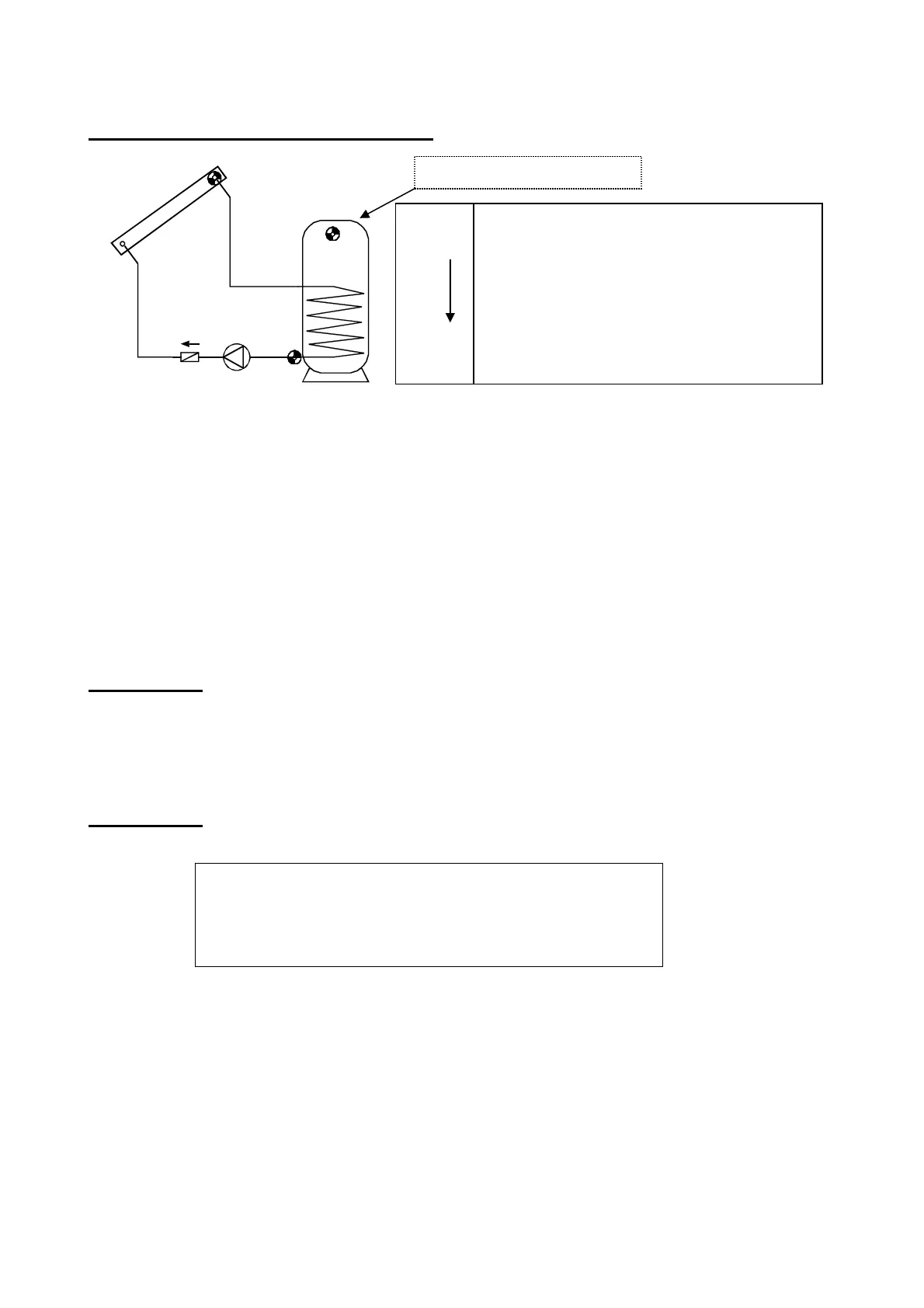
Hydraulic diagrams
Solar thermal system - program 0 = factory settings
The solar pump A runs when S1 has a temperature of diff higher than S2 and S2 has not
exceeded the threshold max.
In addition, the pump’s protective function takes effect: During a standstill, steam can oc-
cur in the system. When automatically switched on again, the pump does not have the re-
quired pressure in the steam phase to lift the fluid level to the collector’s supply line (highest
point in the system). This represents a considerable load on the pump. The collector’s excess
temperature shut-down function can be used to block the pump whenever a certain tempera-
ture has been reached at the collector’s sensor until a second threshold, which can also be
set, is fallen short of again. The settings ex works are 130°C for the blockage and 110°C for
the release. The settings can be changed in the menu MEN, sub-menu SYS PF/CET (collec-
tor excess temperature).
Program 1:
With this program, the solar thermal system has an additional storage limit max2 via sen-
sor S3. There is no guarantee that the actual storage temperature will lead to a cut-off in
time, especially if the reference sensor S2 is installed at the return outlet for the heat ex-
changer.
Program 2:
As program 0, however with additional 10 V burner requirement via S3 at control output.
A = S1 > (S2 + diff) & S2 < max
Control output COP: 10 V = S3 < min2 (burner on)
0 V = S3 > max2 (burner off)
Subsequently, an auxiliary relay can be connected to the control output HIREL-STAG, which
forwards the burner requirement in potential-free format. The active control output is indicat-
ed by the flashing burner symbol in the display.
S1
S2
max
diff
Required settings :
max … limit TK S2
max2 … see program 1 or 2
min2 … see program 2
diff … coll. S1 – TK S2
Additional required settings:
max2 … COP off (0V) S3 (ex works = 65°C)
min2 … COP on (10V) S3 (ex works = 40°C)
S3 for program 1 and 2
 Loading...