1-1
Waveforms may be acquired in NORMAL, ENVELOPE,
and AVG (averaging) Modes. NORMAL Mode provides a
continuous acquisition display similar to that seen with an
analog oscilloscope. AVG (averaging) Mode is especially
useful for improving the signal-to-noise ratio of the
displayed waveform by averaging from 2 to 256 acquisi-
tions to remove uncorrelated noise. REPETITIVE Mode
The record length of acquired waveforms is 1024 data
points (512 max/min pairs in ENVELOPE Mode), of which
500 make up a one-screen display (50 data points per divi-
sion for 10 divisions). The entire record may be viewed by
using the Horizontal POSITION control to position any por-
tion of the record within the viewing area.
The amount of pretrigger data displayed is selectable
by choosing the trigger point position within the waveform
record. Five pretrigger lengths are selectable, beginning at
one-eighth of the record length and increasing to seven-
eighths of the record length. Trigger position is independ-
ently selectable for the A and B acquisitions. Additional
trigger positions within the record are selectable via the
GPIB interface commands.
Trigger MODE choices are AUTO LEVEL, AUTO
(ROLL), NORM, and SINGLE SEQ (single sequence) for
the A and A INTEN Horizontal Modes. Triggerable After
Delay and Runs After Delay are provided for the B Hor-
izontal Mode. AUTO LEVEL provides for automatic trigger-
ing on the applied trigger signal. AUTO Mode produces an
auto trigger if a trigger signal is either not received within a
defined time or is inadequate to produce a triggering
event. When triggering conditions are met, normal trigger-
ing occurs. At SEC/DIV settings of 100 ms per division
and slower, AUTO Mode becomes ROLL Mode. NORM
(normal) Mode requires that the triggering signal meet all
the triggering requirements before an acquisition trigger
will be generated. In SINGLE SEQ Mode, a single com-
plete acquisition is done on all called-up VERTICAL
MODES, and the 2430 switches to the SAVE Mode.
A-B (A and B both) and LINE (power-source frequency).
Trigger CPLG selections are AC, DC, HF REJ, LF REJ,
and NOISE REJ. The Trigger LEVEL control amplitude set-
ting is displayed in the crt readout. The Video Option adds
a CPLG selection of TV that processes applied composite
video signals for stable triggering. With the Video Option
installed, the Trigger LEVEL control becomes the TV LINE
number selector for FLD1 and FLD2 triggering.
A choice of VERT, CH1 or CH2, EXT1 or EXT2, LINE,
and A-B or WORD (16-bit data word recognition) for the A
Trigger signal SOURCE provides a wide range of special-
ized triggering capabilities. The B Trigger SOURCE
choices are similar to the A Trigger SOURCE, but exclude
Horizontal Display Modes of A, A INTEN, and B
Delayed are available. Two types of delay operation are
available: B Delayed by Time and A Delayed by Events.
The time base has 28 calibrated SEC/DIV settings in a 1-
2-5 sequence from 5 ns per division to 5 s per division. An
External Clock Mode is provided that accepts clocking sig-
nals from 1 MHz to 100 MHz.
The two vertical channels have calibrated deflection fac-
tors from 2 mV to 5 V per division in a 1-2-5 sequence of
14 steps. Use of coded probes having attenuation factors
of 1X, 10X, 100X, and 1000X extends the minimum sensi-
tivity to 5,000 V per division (with the 1000X probe) and
the maximum sensitivity to 200 J.l.Vper division (using a 1X
probe in SAVE or AVERAGE expanded mode).
VOLTS/DIV readouts are automatically switched to display
a correct scale factor when properly coded probes are
attached.
The 2430 is capable of simultaneous acquisition of the
Channel 1 and Channel 2 input signals. It has a real-time
useful storage bandwidth of 40 MHz for single-event
acquisitions and an equivalent-time bandwidth of 150 MHz
for repetitive acquisitions. Since both channels are
acquired simultaneously, the XY display is available to full
bandwidth.
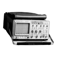
The TEKTRONIX 2430 Digital Oscilloscope is a port-
able, dual-channel instrument with a maximum digitizing
rate of 100 megasamples per second. The instrument is
microprocessor controlled, menu driven, and displays crt
readouts of the vertical and horizontal scale factors,
trigger levels, trigger source, and cursor measurements.
Menu-driven modes of the instrument are selected by
pressing a bezel button under the menu choices displayed
at the bottom of the crt. Selection of a mode is indicated
by an underscoring of the menu choice in the display. The
menus, system operating modes, and auxiliary functions
are described in Section 3 of the Operators Manual, "Con-
trols, Connectors, and Indicators."
INTRODUCTION
SPECIFICA TION
Section 1-2430 Service

 Loading...