3-57
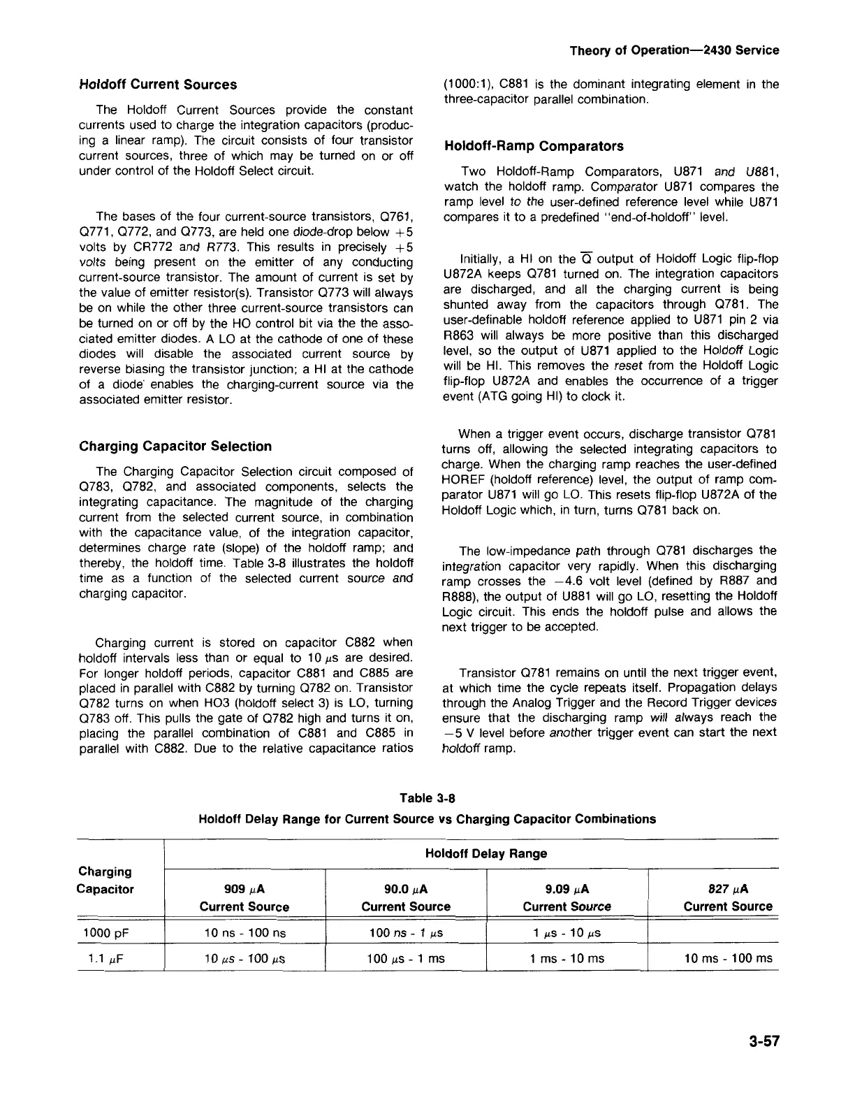
Holdoff Delay Range
Charging
Capacitor
909 J.LA 90.0J.LA 9.09 J.LA 827 f./-A
Current Source
Current Source Current Source
Current Source
1000 pF 10 ns - 100 ns
100 ns - 1 J.LS 1 J.LS- 10 J.LS
1.1 J.LF 10f./-s-100J.Ls 100 J.LS- 1 ms
1 ms - 10 ms
10 ms - 100 ms
Table 3-8
Holdoff Delay Range for Current Source vs Charging Capacitor Combinations
Transistor
0781
remains on until the next trigger event,
at which time the cycle repeats itself. Propagation delays
through the Analog Trigger and the Record Trigger devices
ensure that the discharging ramp will always reach the
- 5 V level before another trigger event can start the next
holdoff ramp.
The low-impedance path through
0781
discharges the
integration capacitor very rapidly. When this discharging
ramp crosses the -4.6 volt level (defined by R887 and
R888), the output of U881 will go LO, resetting the Holdoff
Logic circuit. This ends the holdoff pulse and allows the
next trigger to be accepted.
When a trigger event occurs, discharge transistor
0781
turns off, allowing the selected integrating capacitors to
charge. When the charging ramp reaches the user-defined
HOREF (holdoff reference) level, the output of ramp com-
parator U871 will go LO. This resets flip-flop U872A of the
Holdoff Logic which, in turn, turns
0781
back on.
Initially, a HI on the 0 output of Holdoff Logic flip-flop
U872A keeps
0781
turned on. The integration capacitors
are discharged, and all the charging current is being
shunted away from the capacitors through
0781.
The
user-definable holdoff reference applied to U871 pin 2 via
R863 will always be more positive than this discharged
level, so the output of U871 applied to the Holdoff Logic
will be HI. This removes the reset from the Holdoff Logic
flip-flop U872A and enables the occurrence of a trigger
event (ATG going HI) to clock it.
Holdoff-Ramp Comparators
Two Holdoff-Ramp Comparators, U871 and U881,
watch the holdoff ramp. Comparator U871 compares the
ramp level to the user-defined reference level while U871
compares it to a predefined "end-of-holdoff" level.
(1000:1), C881 is the dominant integrating element in the
three-capacitor parallel combination.
Theory of Operation-2430 Service
Charging current is stored on capacitor C882 when
holdoff intervals less than or equal to 10 J.Lsare desired.
For longer holdoff periods, capacitor C881 and C885 are
placed in parallel with C882 by turning
0782
on. Transistor
0782
turns on when H03 (holdoff select 3) is LO, turning
0783
off. This pulls the gate of
0782
high and turns it on,
placing the parallel combination of C881 and C885 in
parallel with C882. Due to the relative capacitance ratios
Charging Capacitor Selection
The Charging Capacitor Selection circuit composed of
0783, 0782,
and associated components, selects the
integrating capacitance. The magnitude of the charging
current from the selected current source, in combination
with the capacitance value, of the integration capacitor,
determines charge rate (slope) of the holdoff ramp; and
thereby, the holdoff time. Table 3-8 illustrates the holdoff
time as a function of the selected current source and
charging capacitor.
The bases of the four current-source transistors,
0761,
0771, 0772,
and
0773,
are held one diode-drop below + 5
volts by CR772 and R773. This results in precisely +5
volts being present on the emitter of any conducting
current-source transistor. The amount of current is set by
the value of emitter resistor(s). Transistor
0773
will always
be on while the other three current-source transistors can
be turned on or off by the HO control bit via the the asso-
ciated emitter diodes. A LO at the cathode of one of these
diodes will disable the associated current source by
reverse biasing the transistor junction; a HI at the cathode
of a diode' enables the Charging-current source via the
associated emitter resistor.
The Holdoff Current Sources provide the constant
currents used to charge the integration capacitors (produc-
ing a linear ramp). The circuit consists of four transistor
current sources, three of which may be turned on or off
under control of the Holdoff Select circuit.
Holdoff Current Sources

 Loading...


