5-4
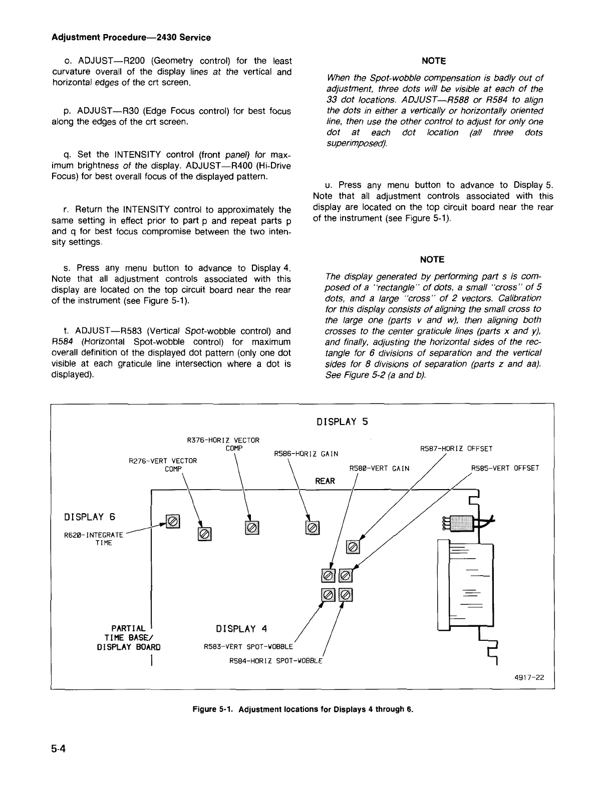
Figure 5-1. Adjustment locations for Displays 4 through 6.
RS84 -HORIZ SPOT -WOBBLE
PARTIAL
TIME BASEl
DISPLAY BOARD
I
R620- IN T EG RATE
TIME
491 7-22
DISPLAY 4
DISPLAY 6
R276 -V ERT VE CT OR
CO MP
RSBS - VE R T OFFSE T
RS86-HO R IZ GAIN
RSB7-H ORIZ OFFSET
DISPLAY 5
R3 7 6 - HORI Z VEC T OR
COM P
The display generated by performing part
s
is com-
posed of a "rectangle" of dots, a small "cross" of 5
dots, and a large "cross" of
2
vectors. Calibration
for this display consists of aligning the small cross to
the large one (parts v and w), then aligning both
crosses to the center graticule lines (parts x and y),
and finally, adjusting the horizontal sides of the rec-
tangle for 6 divisions of separation and the vertical
sides for
8
divisions of separation (parts z and aa).
See Figure 5-2 (a and b).
NOTE
u. Press any menu button to advance to Display 5.
Note that all adjustment controls associated with this
display are located on the top circuit board near the rear
of the instrument (see Figure 5-1).
When the Spot-wobble compensation is badly out of
adjustment, three dots will be visible at each of the
33 dot locations. ADJUST
-R588
or
R584
to align
the dots in either a vertically or horizontally oriented
line, then use the other control to adjust for only one
dot at each dot location (all three dots
superimposed).
NOTE
t.
ADJUST-R583 (Vertical Spot-wobble control) and
R584 (Horizontal Spot-wobble control) for maximum
overall definition of the displayed dot pattern (only one dot
visible at each graticule line intersection where a dot is
displayed).
s. Press any menu button to advance to Display 4.
Note that all adjustment controls associated with this
display are located on the top circuit board near the rear
of the instrument (see Figure 5-1).
r. Return the INTENSITY control to approximately the
same setting in effect prior to part p and repeat parts p
and q for best focus compromise between the two inten-
sity settings.
q. Set the INTENSITY control (front panel) for max-
imum brightness of the display. ADJUST -R400 (Hi-Drive
Focus) for best overall focus of the displayed pattern.
p. ADJUST -R30 (Edge Focus control) for best focus
along the edges of the crt screen.
o. ADJUST -R200 (Geometry control) for the least
curvature overall of the display lines at the vertical and
horizontal edges of the crt screen.
Adjustment Procedure-2430 Service

 Loading...


