6-27
As the power-on diagnostic tests are being performed,
the Trigger LEDs are flashed in a coded sequence to indi-
cate the level of test being run. In a normal sequence with
no failures, the tests run quickly, and the length of time
that an LED is lighted may be very short. If a failure
occurs, the Trigger LEDs are used to flash a binary code
of the FIRST failed test (see Figure 6-5 for the binary
codes of the LEDs). This failure display is important; it
may be the only troubleshooting clue available if, for any
reason, the 2430 cannot display the extended diagnostics
menu.
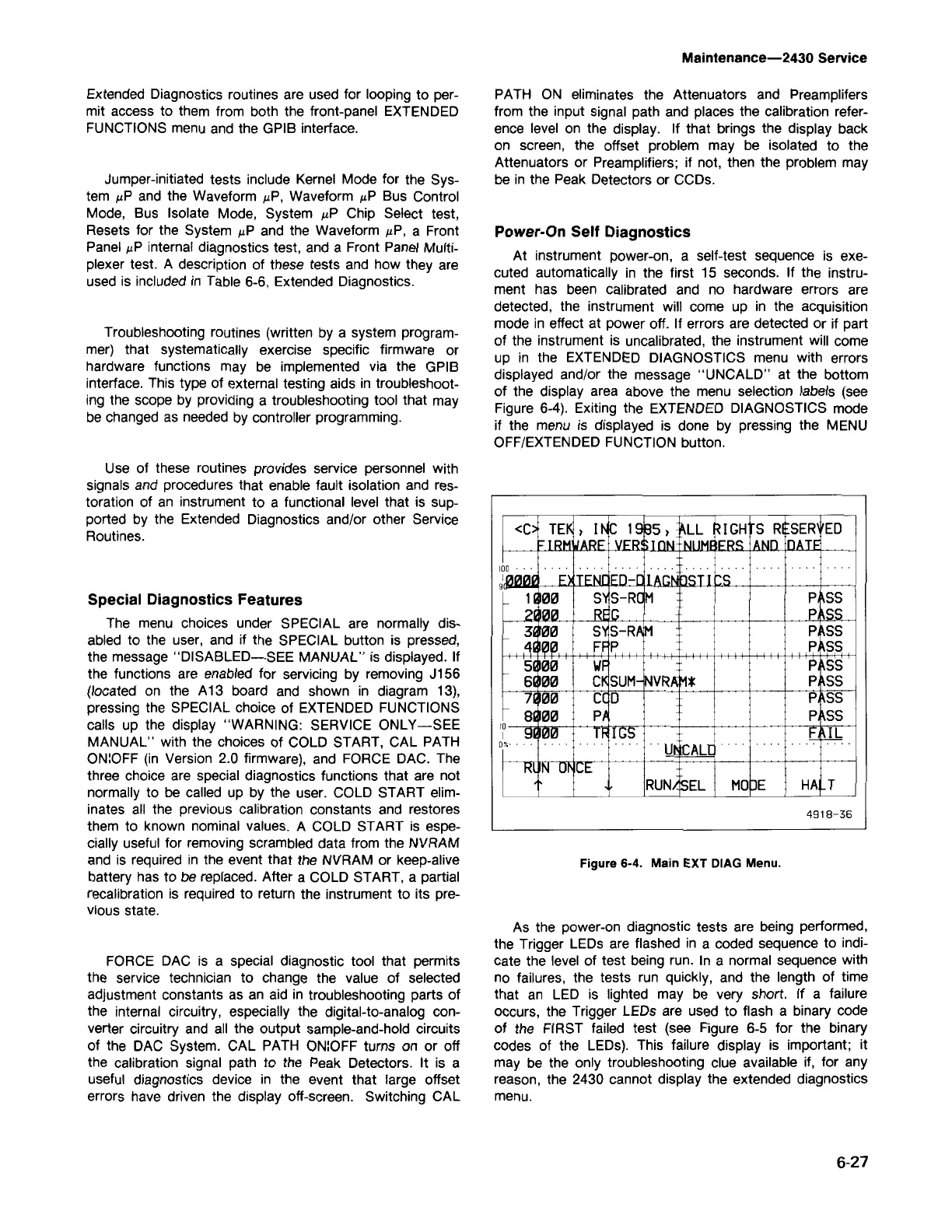
Figure 6-4. Main EXT DIAG Menu.
4918-36
<C
TB
, IN
~ 19
95,
~LL
~IGH
5 RI
5ER ED
!
VJ='R~
;TnN-
-11.111M'
I~RC:
iANn
nATF
1 00 _
.,
..
g l.QII2II2I'
I-. I-.NL
II-.
·n!
Ir:S
isea
5'1
5-ROM
P 55
21 lrara
RE
i G
P
IS5
3 rara
5'15-RA
M
P 55
.~I
I~~.
F .F
P
P 55
51rara
\IF
P
55
61rara
CI<
5UM-
NVRA
M*
P
55
7
rara
ceo
I
P
55
8
rara
PJ P 55
1 0
91
11tJ1tJ _ _
Tii
IIGS
,E
d.b _
I
o~_
_ Ut
IrALt _
Rl
IN
m
ICE
RUN
I
ISEL
MD
DE
HA
T
Power-On Self Diagnostics
At instrument power-on, a self-test sequence is exe-
cuted automatically in the first 15 seconds. If the instru-
ment has been calibrated and no hardware errors are
detected, the instrument will come up in the acquisition
mode in effect at power off. If errors are detected or if part
of the instrument is uncalibrated, the instrument will come
up in the EXTENDED DIAGNOSTICS menu with errors
displayed and/or the message "UNCALD" at the bottom
of the display area above the menu selection labels (see
Figure 6-4). Exiting the EXTENDED DIAGNOSTICS mode
if the menu is displayed is done by pressing the MENU
OFF/EXTENDED FUNCTION button.
PATH ON eliminates the Attenuators and Preamplifers
from the input signal path and places the calibration refer-
ence level on the display. If that brings the display back
on screen, the offset problem may
be
isolated to the
Attenuators or Preamplifiers; if not, then the problem may
be
in the Peak Detectors or CCDs.
Maintenance-2430 Service
FORCE DAC is a special diagnostic tool that permits
the service technician to change the value of selected
adjustment constants as an aid in troubleshooting parts of
the internal circuitry, especially the digital-to-analog con-
verter circuitry and all the output sample-and-hold circuits
of the DAC System. CAL PATH ON:OFF turns on or off
the calibration signal path to the Peak Detectors. It is a
useful diagnostics device in the event that large offset
errors have driven the display off-screen. Switching CAL
Special Diagnostics Features
The menu choices under SPECIAL are normally dis-
abled to the user, and if the SPECIAL button is pressed,
the message "DISABLED-SEE MANUAL" is displayed. If
the functions are enabled for servicing by removing J156
(located on the A13 board and shown in diagram 13),
pressing the SPECIAL choice of EXTENDED FUNCTIONS
calls up the display "WARNING: SERVICE ONLY-SEE
MANUAL" with the choices of COLD START, CAL PATH
ON:OFF (in Version 2.0 firmware), and FORCE DAC. The
three choice are special diagnostics functions that are not
normally to be called up by the user. COLD START elim-
inates all the previous calibration constants and restores
them to known nominal values. A COLD START is espe-
cially useful for removing scrambled data from the NVRAM
and is required in the event that the NVRAM or keep-alive
battery has to be replaced. After a COLD START, a partial
recalibration is required to return the instrument to its pre-
vious state.
Use of these routines provides service personnel with
signals and procedures that enable fault isolation and res-
toration of an instrument to a functional level that is sup-
ported by the Extended Diagnostics and/or other Service
Routines.
Troubleshooting routines (written by a system program-
mer) that systematically exercise specific firmware or
hardware functions may be implemented via the GPIB
interface. This type of external testing aids in troubleshoot-
ing the scope by providing a troubleshooting tool that may
be changed as needed by controller programming.
Jumper-initiated tests include Kernel Mode for the Sys-
tem JIP and the Waveform IlP, Waveform IlP Bus Control
Mode, Bus Isolate Mode, System JIP Chip Select test,
Resets for the System IlP and the Waveform JIP, a Front
Panel IlP internal diagnostics test, and a Front Panel Multi-
plexer test. A description of these tests and how they are
used is included in Table 6-6, Extended Diagnostics.
Extended Diagnostics routines are used for looping to per-
mit access to them from both the front-panel EXTENDED
FUNCTIONS menu and the GPIB interface.

 Loading...


