6-94
5. Adjust the test scope to view the AF signal. It should be a TIL-level square wave with a 50% duty
cycle.
3. Connect CH 1 of a test scope to TP840. Display that signal and use it as a trigger source for the
test scope. This point is the AF address bit (the MSB) of the address bus.
4. Turn the power on and check that the RESET signal on U844 pin 8 is HI; if not, troubleshoot the
Power Up Reset circuitry (schematic diagram 1) and the Power Up circuitry (schematic
diagram 23).
2. Move jumper J127 (Waveform Processor Bus control) from the NORMAL position (pins 1 and 2
connected) to the BUSTAKE position (pins 2 and 4 connected). This places the Waveform Proces-
sor Bus under control of the System J.LP.In the mode, the basic operation of the System J.LPcan
be checked, and all the address decoding circuitry can be verified.
1. With the power off, move jumper J126 from pins 1 and 2 to pins 2 and 3 of P126. This disables
the System J.LPData Bus Driver, and allows the data bus lines to be pulled up and down to a
single-byte instruction. The instruction (CLRB) continually fetches and executes the CLRB instruc-
tion to step through the entire 64 K of addresses.
System J.LPA12U640 (schematic diagram 1) Kernel Test:
Use the System J.LPKernel Test to verify the ability of the System J.LPto function.
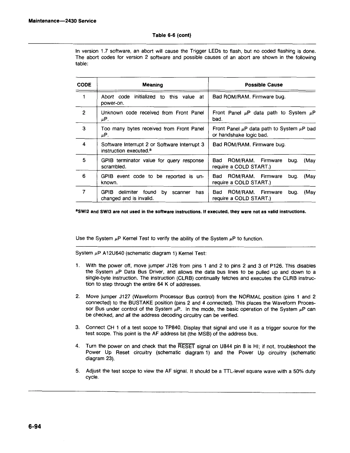
·SWI2 and SWI3 are not used in the software instructions. If executed, they were not as valid instructions.
CODE
Meaning Possible Cause
1
Abort code initialized
to
this value
at
Bad ROM/RAM. Firmware bug.
power-on.
2
Unknown code received from Front Panel Front Panel J.LPdata path to System J.LP
J.LP.
bad.
3 Too many bytes received from Front Panel
Front Panel J.LPdata path to System J.LPbad
J.LP.
or handshake logic bad.
4
Software Interrupt 2 or Software Interrupt 3 Bad ROM/RAM. Firmware bug.
instruction executed.
a
5 GPIB terminator value for query response
Bad ROM/RAM.
Firmware bug. (May
scrambled. require a COLD START.)
6 GPIB event code to be reported is
un-
Bad ROM/RAM. Firmware
bug.
(May
known. require a COLD START.)
7
GPIB delimiter found
by
scanner has
Bad ROM/RAM.
Firmware bug. (May
changed and is invalid.
require a COLD START.)
In version 1.7 software, an abort will cause the Trigger LEOs to flash, but no coded flashing is done.
The abort codes for version 2 software and possible causes of an abort are shown in the following
table:
Table
6-6
(cant)
Maintenance-2430 Service