I
I
I
I
I
I
I
I
I
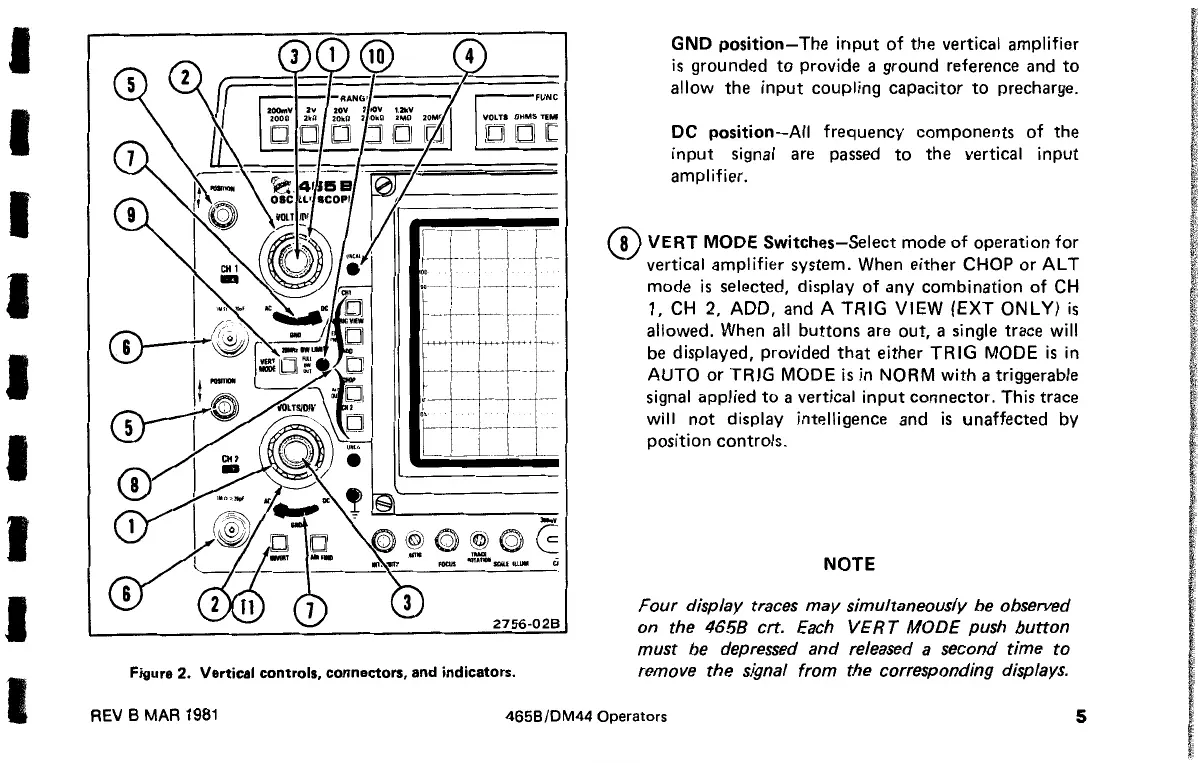
Figure 2. Vertical controls, connectors, and indicators.
GND
position-
The
input
of
the vertical amplifier
is
grounded
to
provide a ground reference and
to
allow the
input
coupling capacitor
to
precharge.
DC
position-All
frequency components
of
the
input
signal
are
passed
to
the vertical
input
amplifier.
(!)VERT
MODE Switches-Select mode
of
operation
for
vertical amplifier system. When either CHOP
orAL
T
mode
is
selected, display
of
any combination
of
CH
1,
CH
2,
ADD,
and A
TRIG
VIEW
(EXT
ONLY)
is
allowed. When all buttons
are
out, a single trace
will
be
displayed, provided
that
either
TRIG
MODE
is
in
AUTO
or
TRIG
MODE
is
in NORM
with
a triggerable
signal applied
to
a vertical
input
connector. This trace
will
not
display intelligence and
is
unaffected by
position controls.
NOTE
Four
display traces
may
simultaneously be observed
on the
4658
crt. Each
VERT
MODE
push
button
must be depressed and released a second time
to
remove the signal from the corresponding displays.
REV B MAR
1981
4658/DM44
Operators
5

 Loading...


