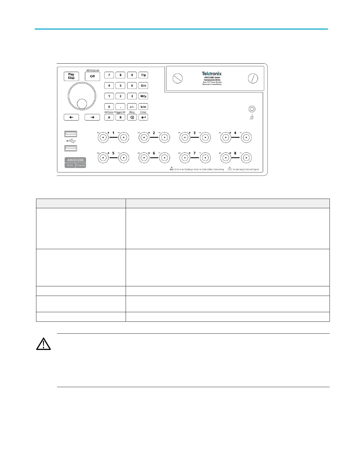
Front-panel connectors
Table 1: Front-panel connectors
Connector Description
Analog outputs (+ and –)
AWG5202 – Two channels
AWG5204 – Four channels
AWG5208 – Eight channels
These SMA type connectors supply the complimentary (+) and (-) analog output signals.
The channel LEDs light to indicate when the channel is enabled and the output is electrically
connected. The LED color matches the user defined waveform color.
The channel (+) and (-) connectors are electrically disconnected when the All Outputs Off
control is activated.
AC outputs (+) The (+) connector of each channel can supply a single-ended analog signal when an AC output
mode is activated for the channel. The AC output provides for additional amplification and
attenuation of the output signal.
The (-) connector of the channel is electrically disconnected. For best EMI reduction, install a
50 Ω termination to the (-) connector when using the AC output mode.
USB Two USB2 connectors.
Removable hard disk drive (HDD) The HDD contains the operating system, product software and all user data. By removing the
HDD, user information such as setup files and waveform data is removed from the instrument.
Chassis ground Banana type ground connection.
CAUTION. Always turn off the signal outputs when you connect or disconnect cables to/from the signal output connectors. Use
the All Outputs Off button (either the front-panel button or the screen button) to quickly disable the Analog and Marker outputs.
(Marker outputs are located on the rear panel.) When the All Outputs Off is enabled, the output connectors are electrically
disconnected from the instrument.
Do not connect a DUT to the front-panel signal output connectors when the instrument signal outputs are on.
Do not power on or off the DUT when the generator signal outputs are on.
Operation basics
AWG5200 Series Installation and Safety Instructions 21

 Loading...


