Getting Acquainted with the Oscilloscope
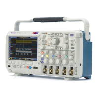
14. For digital channels (MSO2000 series
only), the baseline indicators label the
channel, and point to the high and low
levels. The colors follow the color code
used on resistors. The D0 indicator is
black, the D1 indicator is brown, t he
D2 indicator is red , and so on.
The b us display shows decoded packet
level information for serial bu ses or for
parallel buses (MSO2000 series only). The
bus indicator shows the bus number a nd
bus type.
Not shown in this illustration, the Timing
Resolution readout shows the timing
resolution of the digital channels. To see
the readout, push the D15-D0 front pane l
button.
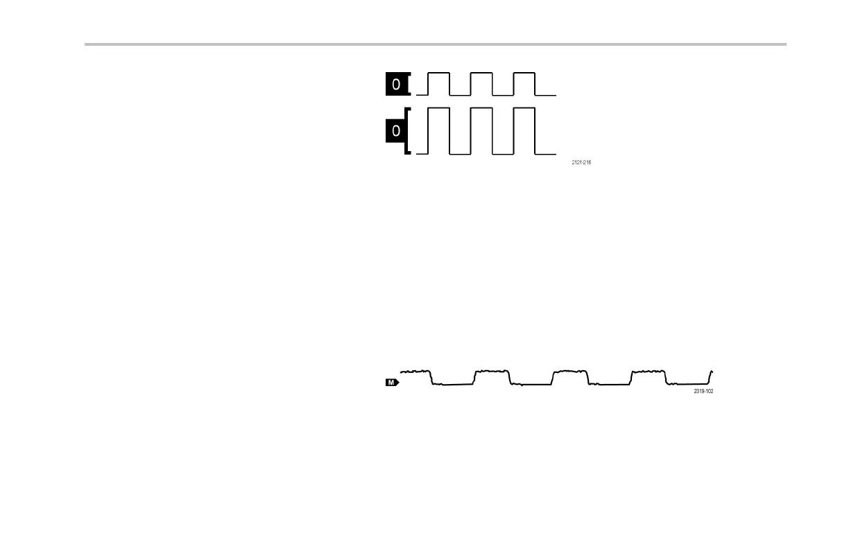
15. For math channels, the waveform baseline
indicator shows the zero-volt level of a
waveform.
DPO2000 and MSO2000 Series Oscilloscopes User Man ual 69
 Loading...