Acquire the Sign
al
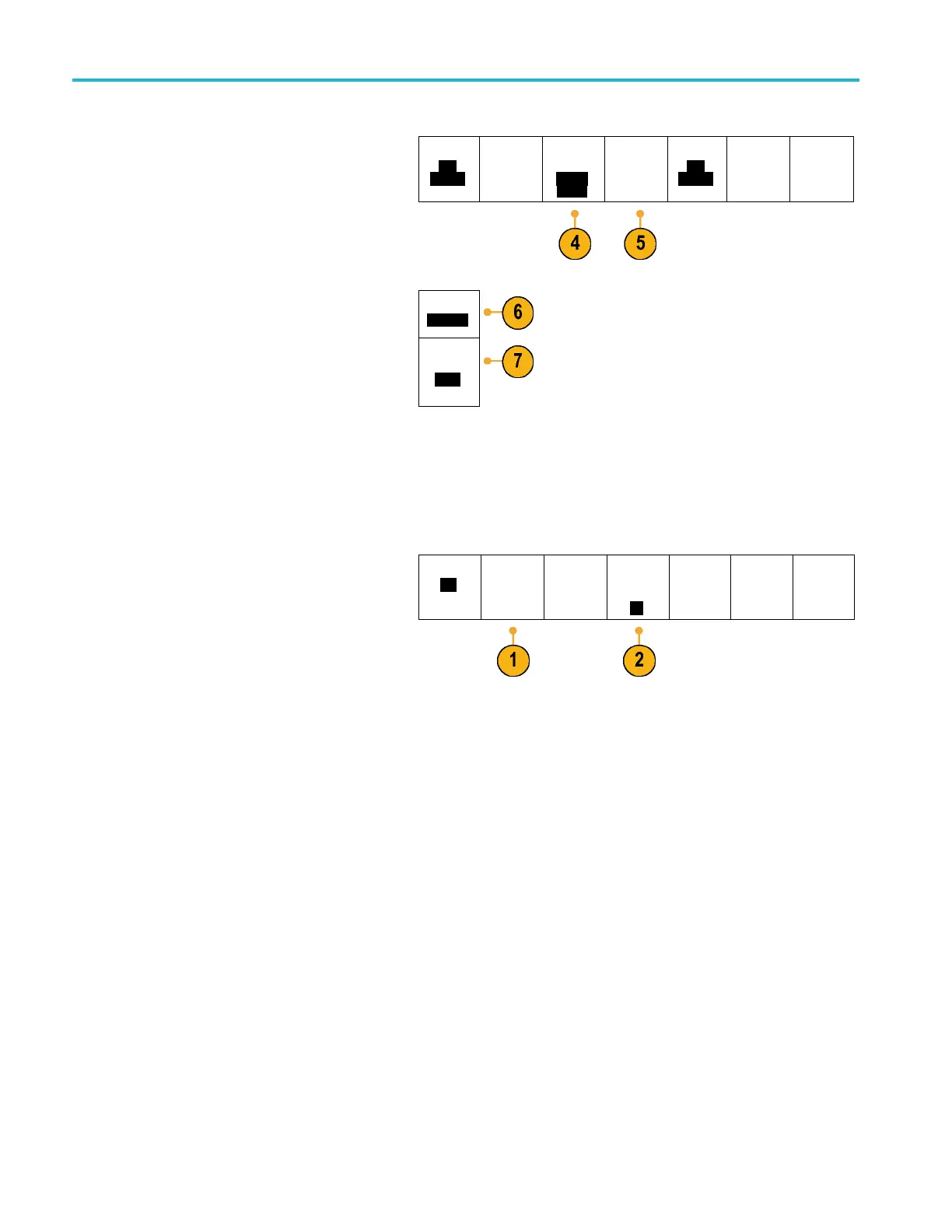
4. Push Thresholds to configure the high and
low thresholds for the ARINC429 bus being
acquired or se
lect from available presets.
Bus B1
AR-
INC429
Define
Inputs
Thresh-
olds
800mV
0.00 V
Configure
B1 Label
AR-
INC429
Bus
Display
Event
Table
5. Push Configure and select the appropriate
side menu choi
ces.
Bit Rate
100 kbps
6. Push Bit Rate, and turn Multipurpose a to
select from
the list of predefined bit rates.
Alternatively, you can set the bit rate to a
specific value. To do so, select Custom, and
then turn Mu
ltipurpose b to set the bit rate
from 10 kbps to 1 Mbps
DATA
Format
DATA
7. Push DATA f
ormat, and turn Mu ltipurpose a to select from the size of the data field for packets being decoded on
the ARINC429 bus.
I
2
CBus
To acquire data from an I
2
C bus, you need to also set up these items:
1. If you select I2C, push Define Inputs and the
appropriate side menu choices.
Bus B1
I2C
Define
Inputs
Thresholds Include
R/W in
Address
No
B1 Label
I2C
Bus
Display
Event
Table
You can assign the predefined SCLK Input
or SDA Input to the channel connected to
the signal.
2. Push Include R/W in Address and then
push the desired side button.
This control determines how the oscilloscope
shows the I
2
C addresses in bus decode
traces, cursor readouts, Event Table listings,
and trigger settings.
If you select Yes, the oscilloscope displays 7-bit addresses as eight bits, w here the eighth bit (LSB) i s the R/W bit. It
displays 10-bit addresses as 11 bits where the third bit is the R/W bit.
If you select No, the oscilloscope displays 7-bit addresses as seven bits, and 10-bit addresses as ten bits.
In the physical layer of the I
2
C protocol, 10 bit I
2
C addresses are preceded by the five bit code, 11110. The oscilloscope
does not include these five bits in address readouts.
72 MDO3000 Series Oscilloscopes User Manual
 Loading...


