TM 11-6625-2980-14
Section 1-PG 508
OPERATING
INSTRUCTIONS
Instrument Description
The PG 508 is a 50 MHz general purpose full
function pulse generator usable in all TM 500-series
power modules except the TM 501. It is compatible with
MOS and other general purpose circuitry. Important
features of the instrument include independent period
and duration controls with a control error light,
independent pulse top and bottom level controls,
variable leading and trailing transition time adjustments,
and fully adjustable pulse delay capabilities. Front panel
controls and connectors provide a trigger or
synchronous gate input with level and slope controls,
square wave output and complementary pulse output for
high duty factors. Delayed and paired pulse and manual
trigger or gate capabilities are also provided. All inputs
and outputs are internally terminated in 50 n except the
TRIG/GATE input which is internally selectable for
either 50 n or 1 Mn, 20 pF input impedance. Special
positions on PERIOD, DURATION, DELAY, and
TRANSITION controls permit customized control
ranges.
The front panel is color coded for easy reference to
controls and their associated functions. Green indicates
triggering functions and blue indicates mode functions.
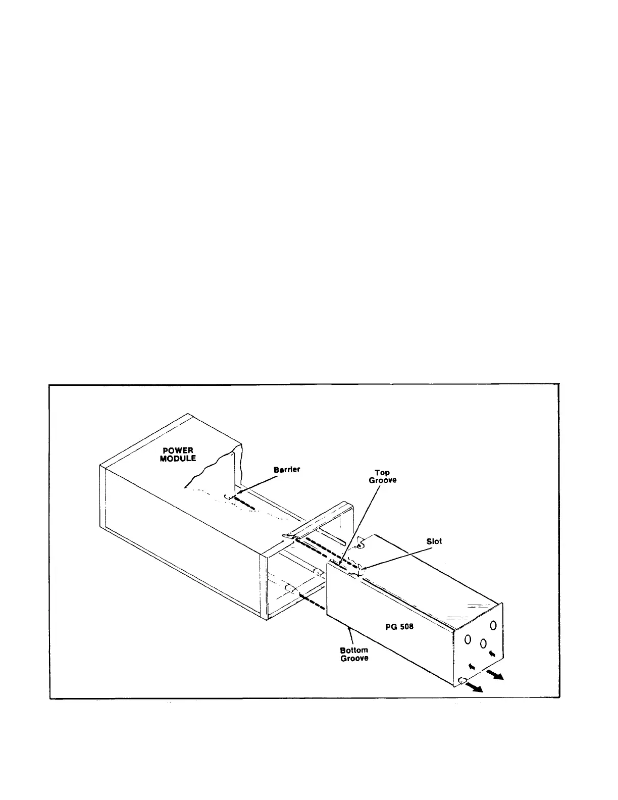
Installation and Removal
The PG 508 is calibrated and ready for use when
received. It operates in any two compartments of the TM
500-series power modules. See Appendix A for line
voltage requirements and power module operation. Fig.
1-1 shows the installation and removal procedure. Make
certain the power module is off when inserting or
removing the PG 508. Check that the PG 508 is fully
inserted in the power module. Pull the power switch on
the power module. The POWER light on the PG 508
should now be on. Refer to the Controls and Connectors
foldout page in Section 4 of this manual for a complete
description of the front panel controls and connectors.
Fig. 1-1. PG 508 installation and removal.
1-1
 Loading...
