TM 11-6625-2980-14
Using the Rear Interface
Connectors
See the accompanying chart for rear interface
connector assignments For other functions not detailed
here the small auxiliary board (E) has numerous
connectors available Use the connections to make
custom inputs or outputs to the PG 508 through the
Power Module
Amplitude Monitor
These pins (25A) are connected to the OUTPUT
terminal through a 27 k resistor and ground (26A) To
use this function place the PERIOD control in the EXT
TRIG OR MAN position and connect an accurate
voltmeter to these terminals Now adjust the TRIG/GATE
LEVEL control cw for the high steady state output
voltage and ccw for the low steady state output voltage
In this manner the output pulse amplitude levels may be
precisely monitored.
External Level Control Inputs
See the discussion under the heading External
Voltage Control in Section 1 of this manual for use of
these terminals
Trig/Gate Input
These assignments provide rear interface input
capabilities for the front panel TRIG/GATE IN input. The
signal lead (24B) must be user installed but the ground
(25B) Is factory wired To make the proper connections
remove the cable extending from the TRIG/GATE IN
connector to the input board by pulling the end from the
socket on the board Install a twelve inch cable with the
proper connectors, Tektronix Part No 175-1827-00, from
the connector on the input circuit board labeled
Trig/Gate In to the other connector on the output board
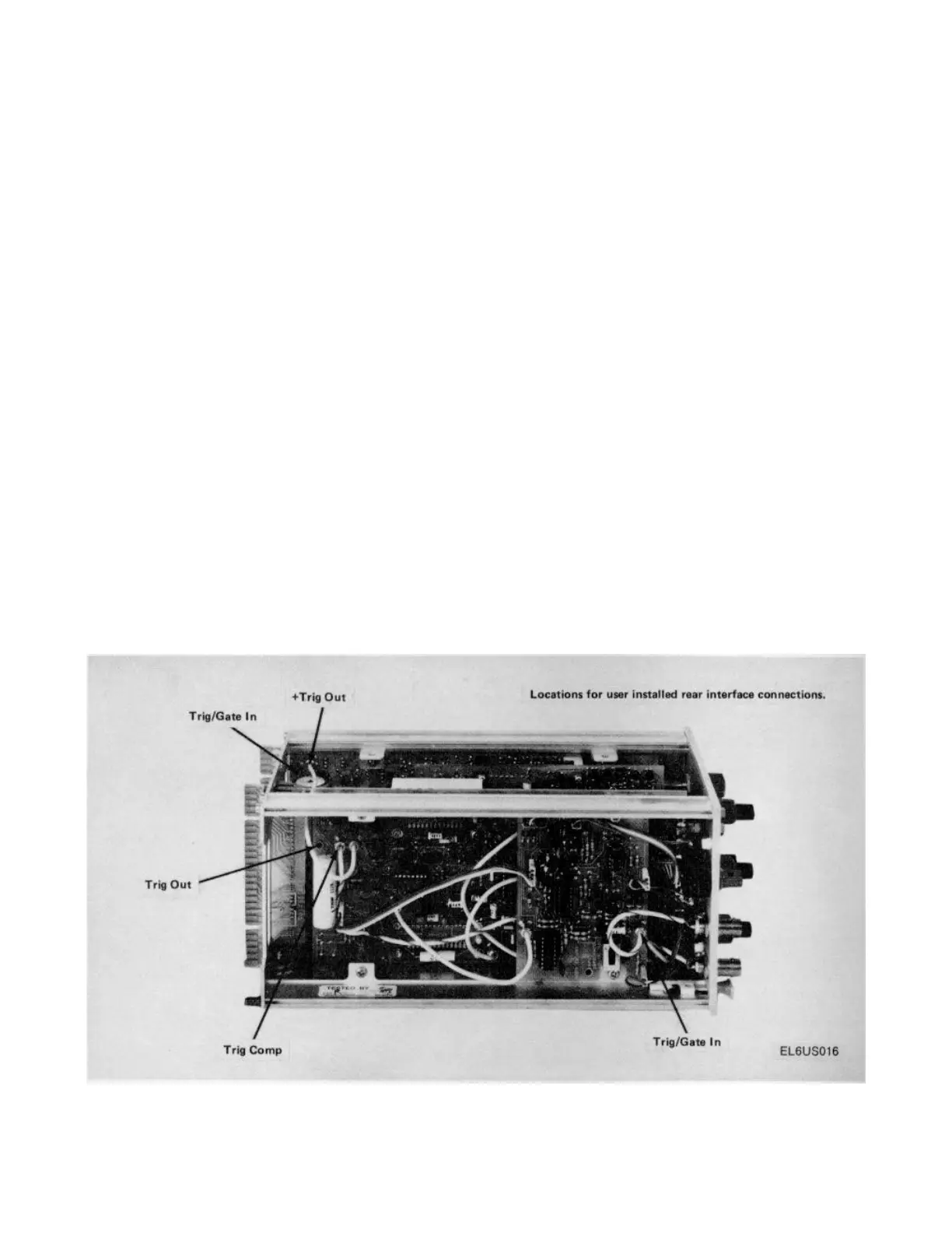
labeled Trig/Gate In as shown in the illustration.
Trigger Output
The hot or signal lead (28B) must be user installed
while the ground (27B) is factory wired To route this
function through the rear interface connector remove the
plug on the timing circuit board connected to the cable
from the - TRIG OUT front panel connector This plug is
shown on the illustration and is labeled Trig Out.
Connect a six inch cable with the proper connectors,
Tektronix Part No. 175-1824-00, from the connector
labeled Trig Out in the illustration to the connector on
the output board labeled - Trig Out in the illustration To
obtain the complement trigger out signal connect the
coaxial cable to the connector labeled Trig Comp in the
illustration. The normal trigger output may be used
simultaneously with the complement, through the rear
connector, without disturbing the operation of either
Figure 9. Locations for user installed rear interface
connections.
Figure 9 . Locations for user installed rear interface connections .
1-12
 Loading...
