Theory of operation
General
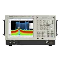
A processor system controls the instrument. The instrument features an XGA
resolution flat-panel display, a transparent touch-screen, and a front-panel with
direct acces
s to common features. You c an also use the instrument with a mouse
or other pointing device, and/or a keyboard.
The instrum
ent uses the Microsoft Windows 7 operating system.
Signal path and processing
RF signal path
An RF sign
al enters the instrument through a direct N-type coaxial connection.
The RF signal path consists of an attenuator, optional preamplifier, 1st converter,
and 2nd c
onverter. The purpose of the RF signal path is to translate a b and-limited
replica of a portion of the input signal range to an intermediate frequency (IF)
which can be sampled by a high-dynamic-range A/D converter.
The processor system controls the RF signal path.
Acquisition system
The acquisition system samples the IF signal and converts it to digital signals.
These
digital signals are then filter ed numerically and processed either for
direct display or by measurement applications to provide signal quality metrics
to the user. The acquisition data processing is performed by one of several
field-programmable gate arrays (FPGAs) under control of the processor. The
processor performs m easurement applications.
Processor system
The processor system consist s of a COM E xpress PCI-based proce ssor board and
a Digital interface board that connects the processor to the acquisition board.
Trigger inputs
There are two coaxial trigger inputs. One is on the front panel below the display
and the other is on the rear panel. Both trigger inputs c onnect directly to the
Digital interface board. Trigger signals are processed by an FPGA on the Digital
interface board. The information from the trigger system is combined with
acquisition data by the processor system.
The Trigger Out signal is a coaxial connection on the front panel below the
display. The trigger out signal comes from the Acquisition Control FPGA,
through the Digital interface board.
1–2 RSA5100B Series Service Manual

 Loading...


