Removal and installation procedures
Trim, cabinet, and module removal
Use the following two tables to determine items of the instrument that you will
need to remove to acc ess replaceable parts. The fi rst table lists items that may
need to be removed before you can ac cess a replaceable module. The second
table lists customer replaceable modules and which items must be removed
to access th
e replaceable module. The approximate location of the primary
customer replaceable modules is shown in the following figure. (See Figure 3-1
on page 3-10.)
Ta ble 3-4: Legend for accessing modules table
A - Front Cover (if installed) F - Internal Cover, top
K - Front Panel
B - Front panel trim
G - Internal Cover, bottom L - Internal HDD (if installed)
C - Pouch (if installed) H- Removable HDD (if installed) M - Power Conversion board
D - Cabinet, top
I- Removable HDD Frame
N- Power Supply
E - Cabinet, bottom
J-DisplayAssembly
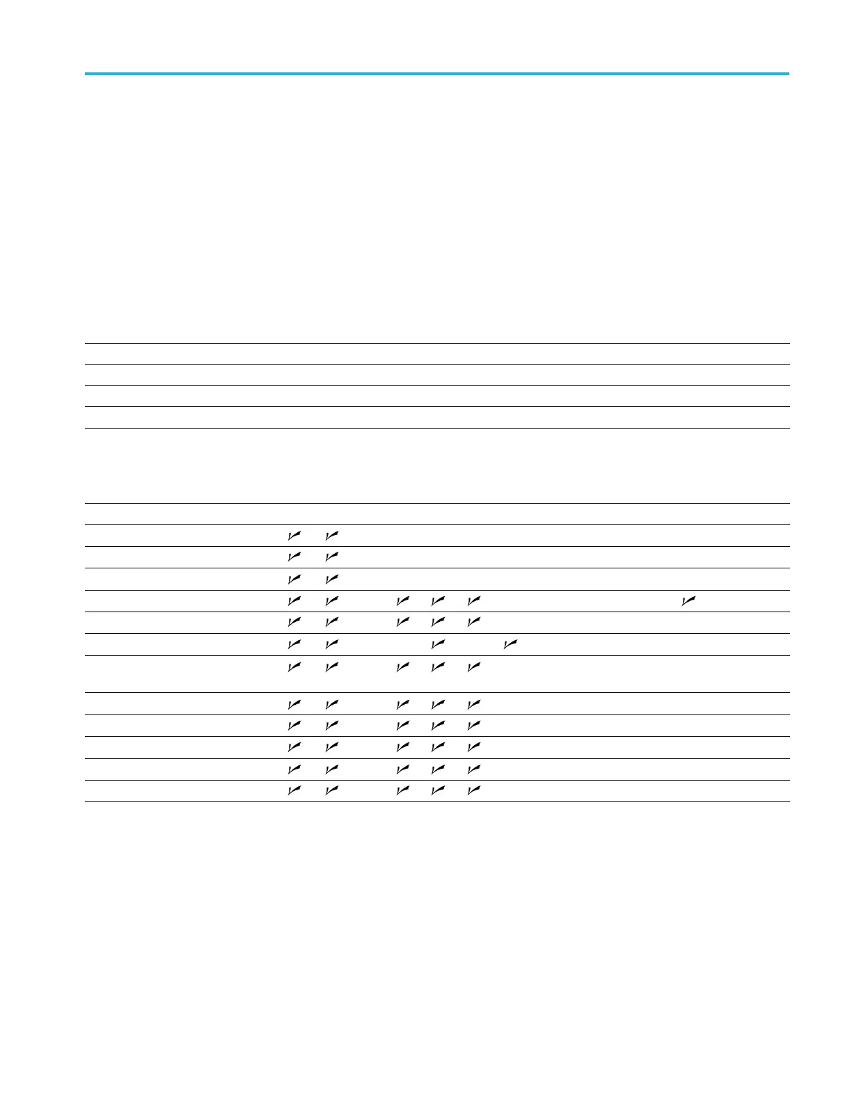
Table 3-5: Accessing modules
Remove these item s to access the module
Modules to replace A B C D E F G H I J K L M N
Disp
lay Assembly
Front Panel
Removable HDD Drive (if installed)
Removable HDD Frame
Digi
tal Fan Tray (Upper Deck)
RF Deck Fan Tray
Real Time IQ/IF Output Acquisition
board (if installed)
RTT/DPSA board
COM-Express PC board
Int
ernal HDD (if installed)
Power Conversion board
Power Supply
RSA5100B Series Service Manual 3–9
 Loading...


