Home
Tektronix
Test Equipment
TBS1000 Series
Tektronix TBS1000 Series User Manual
4
of 1
of 1 rating
126 pages
Give review
Manual
Specs
To Next Page
To Next Page
To Previous Page
To Previous Page
Loading...
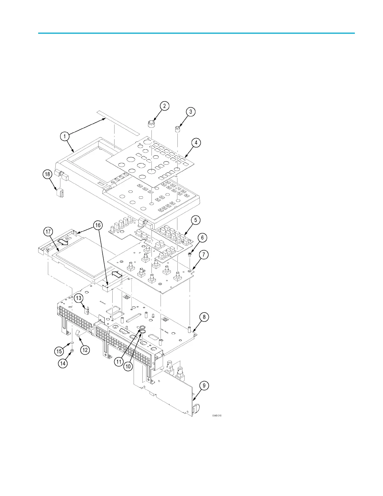
Replaceable
Parts
Parts
Lists
and
Exploded
Views
The
following
tables
show
the
module-level
exploded
views
of
the
TBS1000
oscilloscopes.
Following
ea
ch
exploded
view
is
the
lis
t
of
c
om
ponents,
indexed
by
the
numbers
in
the
fi
gure.
Figure
8-1:
Exploded
diagram,
2-channel
models
TBS1000
Series
Oscilloscope
Service
Manual
8–3
112
114
Table of Contents
Table of Contents
5
General Safety Summary
10
Service Safety Summary
12
Preface
13
Manual Conventions
13
Related Documentation
13
Specifications
15
Signal Acquisition System Characteristics
17
Table 1-1: Signal Acquisition System Characteristics
17
Time Base System
22
Table 1-2: Time Base System
22
Triggering System
24
Table 1-3: Triggering System
24
Display Specifications
28
Table 1-4: Display Specifications
28
Interfaces and Output Ports Specifications
29
Data Handling Characteristics
29
Power Distribution System
29
Table 1-5: Interfaces and Output Ports Specifications
29
Table 1-6: Data Handling Characteristics
29
Table 1-7: Power Distribution System
29
Mechanical Characteristics
30
Environmental Performance
30
Data Logging System Characteristics
30
Table 1-8: Mechanical Characteristics
30
Table 1-9: Environmental Performance
30
Limit Testing System Characteristics
31
Table 1-10: Data Logging System Characteristics
31
Table 1-11: Limit Testing System Characteristics
31
Where to Find Operating Information
33
Theory of Operation
37
System Level Block Diagrams
39
Figure 3-1: Module-Level Block Diagram (2-Channel)
39
Figure 3-2: Module-Level Block Diagram (4-Channel)
40
Main Board
41
Acquisition System
41
Processing and Display System
42
Input Signal Interface
42
Probe Compensation
42
External Trigger
42
Main Board Power
42
Power Supply
42
Display Module
43
Front Panel
43
Performance Verification
45
Required Equipment
47
Table 4-1: Performance Verification
47
Test Record
48
Table 4-2: Test Record
48
Performance Verification Procedures
49
Self Test
49
Self Calibration
49
Check DC Gain Accuracy
49
Check Bandwidth
51
Check Sample Rate Accuracy and Delay Time Accuracy
52
Check Edge Trigger Sensitivity
53
Check External Edge Trigger Sensitivity
55
Check Vertical Position Accuracy
56
Figure 4-1: Example of a Line Graph for the Vertical Position Accuracy Test
59
Adjustment Procedures
61
Required Equipment
63
Adjustment Procedure
63
Table 5-1: Required Equipment
63
Enable the Service Menu
64
Figure 5-1: Adjustment Setups
65
Adjustment Procedure
66
Table 5-2: Adjustment Steps
67
Maintenance
71
Preventing ESD
71
Inspection and Cleaning
71
General Care
72
Interior Cleaning
72
Exterior Cleaning
72
Exterior Inspection
73
Interior Inspection
73
Table 6-1: External Inspection Checklist
73
Cleaning Procedure, Interior
74
Table 6-2: Internal Inspection Checklist
74
Removal and Installation Procedures
76
Summary of Procedures
76
Rear Feet
76
Flip Feet
76
Front-Panel Knobs
76
Rear Case
76
Front Feet
76
Figure 6-1: Locator for Trim and Cabinet Removal (2-Channel Model Shown)
77
Figure 6-2: Locator for Internal Modules (2-Channel Model Shown)
77
Power Supply Module
82
Internal Assembly
83
Figure 6-3: Main Board with the Display Adapter (Refer To: Service Manual 077-0772-00)
84
Front-Panel Cable
85
Main Board Module (Without the Display Adapter Module)
86
Figure 6-4: Instrument Cable Locations (Main Board Without the Display Adapter Module)
87
Display Module
89
Front-Panel Module
90
Keypad
91
Troubleshooting
92
Adjustment after Repair
92
Required Tools and Equipment
92
Troubleshooting Tree
92
Table 6-3: Tools and Equipment
92
Figure 6-5: Oscilloscope Troubleshooting Tree
93
Figure 6-6: Oscilloscope Troubleshooting Tree
94
Figure 6-7: Oscilloscope Troubleshooting Tree
95
Figure 6-8: Oscilloscope Troubleshooting Tree
96
Probe Comp Output
97
Table 6-4: Probe Comp Output
97
Troubleshooting the Power Supply
98
Table 6-5: Troubleshooting the Power Supply
98
Troubleshooting the Display
99
Troubleshooting the Front Panel
100
Table 6-6: Troubleshooting the Front Panel - Service
100
Table 6-7: Troubleshooting the Front Panel - Service Diag
100
Table 6-8: Troubleshooting the Front Panel - Mfg. Test
100
Table 6-9: Expected Signals at J202
101
Troubleshooting the Main Board
103
Table 6-10: Troubleshooting the Main Board
103
Table 6-11: List of Error Codes
104
Repackaging Instructions
106
Diagrams
107
Figure 7-1: TBS1000 Series Block Diagram
108
Replaceable Parts
109
Parts Ordering Information
111
Using the Replaceable Parts List
112
Table 8-1: Replaceable Parts List
112
Parts Lists and Exploded Views
113
Figure 8-1: Exploded Diagram, 2-Channel Models
113
Table 8-2: Replaceable Parts List, 2-Channel Models
114
Figure 8-2: Exploded Diagram, 4-Channel Models
116
Table 8-3: Replaceable Parts List, 4-Channel Models
117
Figure 8-3: Power Supply Module, Cables, and Wires
118
Table 8-4: Replaceable Parts List; Power Supply Module, Instrument Cables, and Wires
118
Figure 8-4: Exploded Diagram, Back Case and Trim
120
Table 8-5: Replaceable Parts List, Back Case and Trim
121
Appendix A: Example of a Vertical Position Accuracy Test Spreadsheet
123
Sample Filled-In Vertical Position Accuracy Test Spreadsheet
123
Table A-1: Vertical Position Accuracy Test Spreadsheet
123
Other manuals for Tektronix TBS1000 Series
Installation And Safety Manual
127 pages
Safety And Installation Instructions
4 pages
Basic Guide
26 pages
4
Based on 1 rating
Ask a question
Give review
Questions and Answers:
Need help?
Do you have a question about the Tektronix TBS1000 Series and is the answer not in the manual?
Ask a question
Tektronix TBS1000 Series Specifications
General
Brand
Tektronix
Model
TBS1000 Series
Category
Test Equipment
Language
English
Related product manuals
Tektronix TBS1000C Series
218 pages
Tektronix TBS1000B Series
174 pages
Tektronix TBS1022
174 pages
Tektronix TBS1052C
40 pages
Tektronix TBS1052B
174 pages
Tektronix TBS1072B
174 pages
Tektronix TBS1032B
174 pages
Tektronix TBS1052B-EDU
174 pages
Tektronix TBS1102
126 pages
Tektronix TBS1104
126 pages
Tektronix TBS1102B
174 pages
Tektronix TBS1202B
174 pages

 Loading...


