Performance Verification
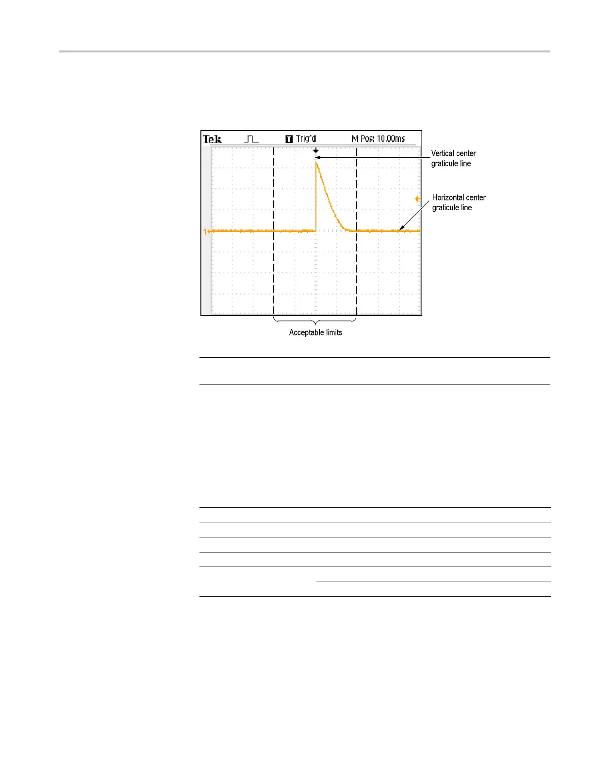
10. Check that the r
ising edge of the marker crosses the center horizontal graticule
line within ±2 divisions of the vertical center graticule line, as shown in the
following figure:
NOTE. On
e division of d isplacement from graticule center corresponds to a
25 ppm time base error.
11. Disconnect the test setup.
Check
Edge Trigger
Sensitivity
This test checks the edge trigger sensitivity for all input channels.
1. Set up the oscilloscope using the following table:
Push
menu button
Sele
ct menu option
Sele
ct setting
Def
ault Setup
——
Cha
nnel 1
Probe 1X
Trig Menu Mode Normal
Acquire
Sample
—
Source Channel under test
Measure
Type Pk-Pk
TDS2000C Series Oscilloscope Service Manual 4–7
 Loading...

