Performance Verification
TDS1000B and TDS2000B Series Oscilloscope Service Manual
4-5
VOLTS/DIV setting DC voltage source output levels Accuracy limits for V
diff
5mV/div +17.5 mV, --17.5 mV 33.6 mV to 36.4 mV
200 mV/div +700 mV, --700 mV 1.358 V to 1.442 V
2V/div +7.00 V, --7.00 V 13.58 V to 14.42 V
5. Set DC voltage source output level to 0V.
6. Disconnect the test setup.
7. Repeat steps 1 through 6 until all input channels have been checked.
This test checks the bandwidth of all input channels.
1. Set up the oscilloscope using the following steps:
Push menu button Select menu option Select setting
DEFAULT SETUP — —
CH 1 Probe 1X
ACQUIRE Average 16
TRIGGER Coupling Noise Reject
MEASURE
Source Channel under test
Type Pk-Pk
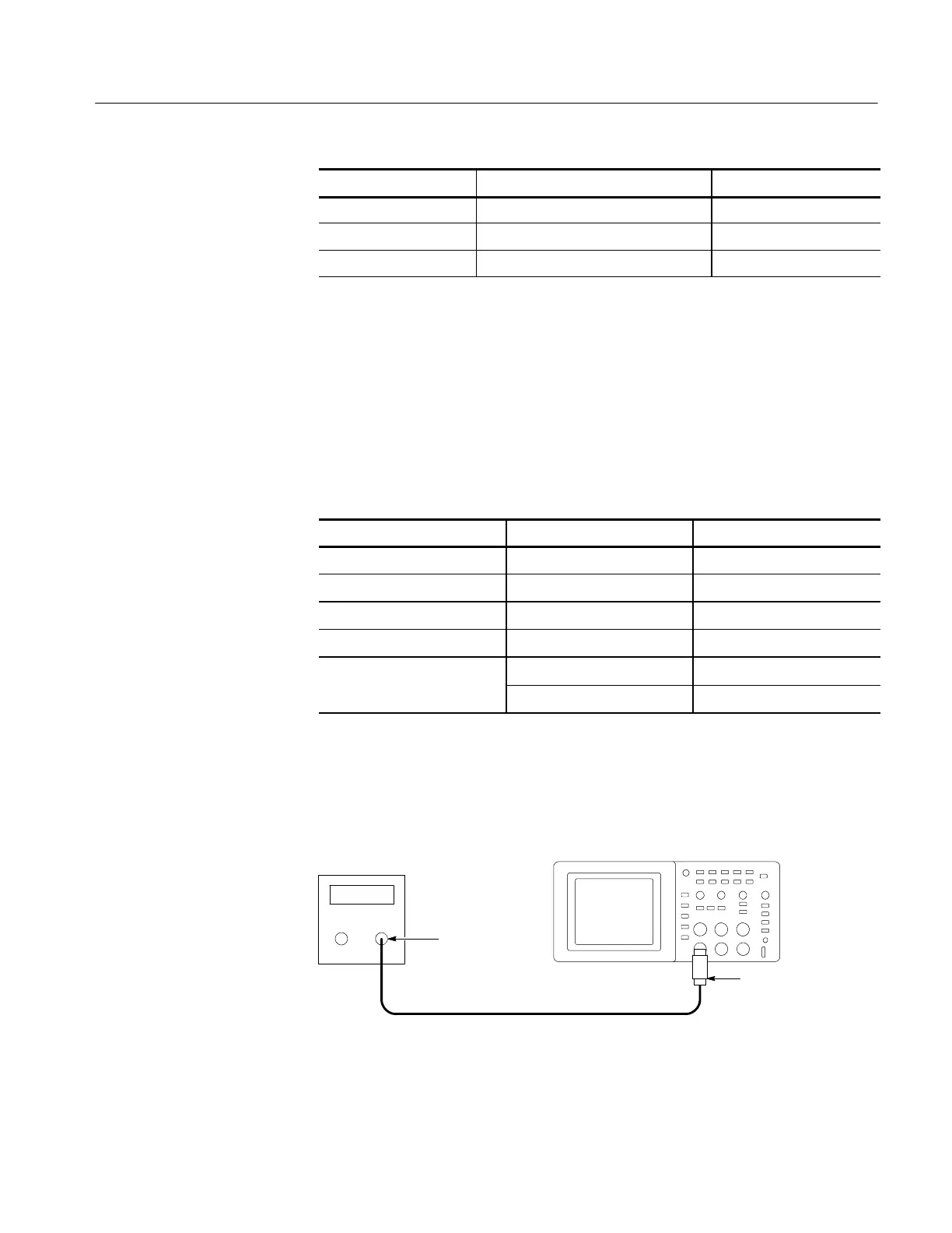
2. As shown below, connect the oscilloscope channel selected in the table to the
leveled sine wave generator.
Digitizing oscilloscope
Leveled
sine wave
generator
50 Ω feedthrough
terminator
BNC cable
Output
3. Set the oscilloscope VOLTS/DIV to 500 mV/div.
4. Set the oscilloscope SEC/DIV to 10 s/div.
Check Bandwidth
 Loading...

