Maintenance
TDS1000B and TDS2000B Series Oscilloscope Service Manual
6-- 25
When the oscilloscope is on and operating properly, the PROBE COMP output
should generate a square wave, approximately 5 V in amplitude, at a 1 kHz
frequency. Use the oscilloscope and set the Attenuation switch to 10X on the
P2220 probe to probe this output.
As shown in the table below, there are two cases of defects. Either the 1 kHz
signal is on and the power supply and main board are both active and functional-
ly capable of doing acquisition, or one of those two modules is not performing
correctly. While a large number of different possible frequencies exist, all
involve detected failures on the main board due to main board failure or power
supply failure.
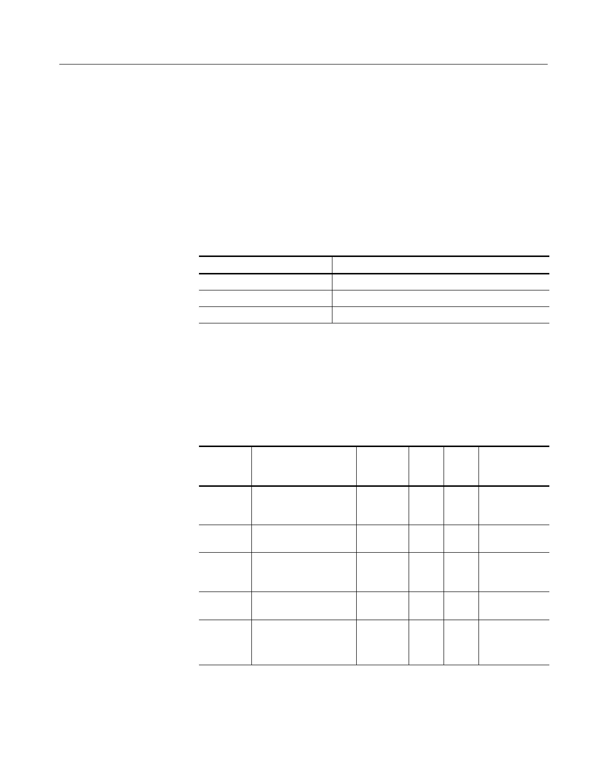
Signal at PROBE COMP Possible problem
1 kHz signal, no display Refer to Troubleshooting the Display (page 6--26)
Non-1 kHz signal Refer to Troubleshooting the Main Board (page 6--32)
No signal Refer to Troubleshooting the Power Supply (page 6--25)
To troubleshoot the power supply, follow these steps:
1. Remove the rear case using the procedure Rear Case on page 6--9.
2. Use the test oscilloscope to measure the voltages from the power supply
module at J101 on the main board module. The table below lists the voltages
you should expect to see.
Supply Voltage range*
Maximum
current
draw
J101
power
pins
J101
return
pins
Derived
supplies
35 V 30 V
DC
to 40 V
DC
floating.
Pin 2 connected to +3.3 V
on the main board.
15 mA 1 2 +28 V LCD
+6 V 5.5 V to 6.5 V 0.7 A 4 3, 5, 8,
10
+5 V
+3.3 V 3.0 V to 3.6 V. Requires
minimum load to maintain
regulation.
1.5 A 6, 7 3, 5, 8,
10
3.3 V, +2.5 V
-- 4 V -- 5 . 0 V t o -- 3 . 5 V 0.8 A 9 3, 5, 8,
10
-- 2 . 5 V
Line trigger --2 V to 6 V open circuit.
±1 diode drop when at-
tached to the main board.
1mA 11 3, 5, 8,
10
Line trigger
PROBE COMP Output
Troubleshooting the
Power Supply
 Loading...

