GB
40
INSTALLATION
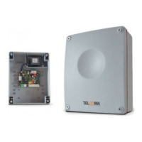
BATTERY CHARGER CB24 (optional)
ELECTRICAL CONNECTIONS
The equipment must be installed "PROFESSIONALLY" by personnel with qualifications as envisaged by current legislation and in compliance with the
standards EN 12453 and EN 12445 governing safety of the automation.
- Ensure that the automation is equipped with end stops and thatthese are correctly sized to suit the overall weight of the gate.
- Fix the control unit on a flat andimmobile surface, suitably protected against the risk of impact andflooding.
For connections, refer to table 1 and figure 2.
In the case of existing systems a general check should be made of the condition of wiring (section, insulation, contacts) and auxiliary equipment
(photocells, receivers, pushbutton panels, key-operated switchesetc.).
Anumber of recommendationsfor a correctelectrical installation are listed below:
- wiring entering the sealed box of the controlunit must maintain, when possible, the initial protection rating ofIP56.
-Thesection of the cables must be calculated on the basis of their length and maximum current.
- Do not use a single “multi-pole” type cable for all connections(line, motors, controls etc.) or in commonwith other equipment.
- Divide the system into atleast two sections,for example:
1) power section (power supply line, motors, flashing light,courtesy light, electric lock) minimum wire section1.5 mm2 (motorline 2.5mm2).
2) signal section (controls, safety contacts,auxiliary power supply)minimum wire section 0.75 mm2
- When very long control cables are used (over50 metres) decoupling is recommended by means of relays installedin the vicinityof the control unit.
-All N.C. inputs (normally closed) not usedin the controlunit must beshorted with thecommon.
-All N.C. contacts associated with the sameinput must beconnected in series.
-All N.O. contacts (normally open) associated withthe same inputmust be connectedin parallel.
- For the control unit power supply, the INSERTION OF AN EXTERNAL DISCONNECT SWITCH (not supplied) is envisaged, which must be
independentand sized according to the load.
A system with the T224 can also operate in the event of a power failure, by the insertion of two 12V 2.2Ah rechargeable batteries (not supplied) and a
battery charger model CB24, all without modifications to therest of thesystem.
It is recommended, in the case of new systems, to connect the battery and battery charger after testing, observing figure 2 and taking special care to
observe wire polarity.
Connection sequence:
- shut offthe230V power supply
- connect terminals 3 and 4 of the CB24to terminals 28and 29 of the control unitT224.
- connect the 2 batteries (in series) with thewires supplied toterminals 1 and 2 of the battery charger.
- ensure that the control unit is powered correctly.
- restore the 230V power supply
-New batteries reach full charge status after approx. 10 hours.
-The number of possible manoeuvres when battery-operated depends on many factors;
asa guideline, around 4 complete cycles are possible in the following conditions:
-gates of 150Kg per leaf
-system with 2 pairs of photocells, plug-in receiver and 1 flashing light (20W max.)
-batteries fully charged
-within 5 hours of failure of the 230V power line
- The control unit slows down the flashing status of the flashing light output in the following condition: battery operation with 230V power
failure.
 Loading...