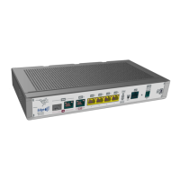
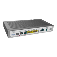
Fig. 25: WAN connectors
Note
WAN connectors do not work during booting and in BIOS mode.
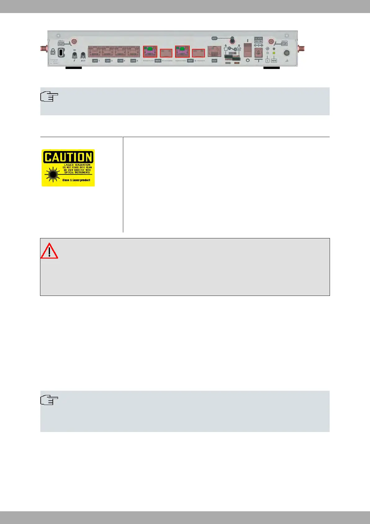
3.7.2.1 Laser information
Chose SFP transceivers that meet the following regulations
• Class 1
• IEC/EN60825-1:2007 2nd Edition or later, European standard
• FCC 21 CFR Chapter 1, Subchapter J (in accordance with FDA and CDRH re-
quirements)
• Application of CE marking in accordance with the 2014/30/EU EMC Directive
and the 2014/35/EU Low Voltage Directive
• UL and/or CSA registered component for North America
• 47 CFR Part 15, Class A
Warning
Laser Radiation. Do not use optical instruments directly or without proper protection. CLASS 1 LASER
PRODUCT
The SFP modules to be installed in the card socket should be class 1 devices that comply with the IEC/
EN 60825-1:2007 standard
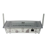
3.7.3 WWAN Antenna Connection (Cell connector)
The M8-Smart has two connectors for WWAN antennas in the rear panel and two connectors for WWAN antennas in
the side panels (on models equipped with this interface).
To assemble or dismantle the antennas, simply screw or unscrew them into or out of the connectors labeled Cell
(located on the rear panel and side panels of the router).
Installing these antennas in the M8-Smart is essential to improve the quality of the signal received and transmitted
by the cellular model.
Note
To achieve high-quality performance, the router should always have the WWAN antennas installed.
For the cellular interface to work, the router needs the corresponding software license.
Some cellular telephony technologies use the antenna diversity technique to improve the quality of the signal re-
ceived. The M8-Smart router family incorporates several WWAN connectors for this.
Teldat S.A.
3 Components and Power Supply
M8-Smart 15
 Loading...