57www.behnke-online.de
GB
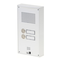
Instructions SIP intercoms series 20-0001BS, 20-0014BS, 20-0016BS
Mounting
Regulations
Please observe the relevant regulations for the
installation of telecommunications and elec-
trical systems and the valid, current standards
and rules of network technology!
.
Note: Dimensioning and installation sketches
can be found at
www.behnke-online.de/bemassung
2.1. 20-0001-BS, 20-0014-BS,
20-0016-BS
Note: When placing the function modules,
please take note of the direction of the alumin-
ium brushing both for aesthetic reasons and
for dampness protection and also follow the
anti-twist protection! The door intercom station
may only be mounted with a frame that matches
the system (series). Prevent condensation
from forming inside the device! Mount the door
intercom station so that no water can remain on
the front panel. When mounting in columns or
housings of other manufacturers, pay special
attention to the ventilation of the column or
housing to prevent condensation in the inter-
com station or in the column or housing (fence
post or similar).
In case you wish to install the electronics
20-0016-BS) in a detached location, please
replace the module housing with an open
counter plate (to be ordered separately) for the
appropriate front frame.
When installing reverse-side mounting com-
ponents, follow the corresponding installation
instructions.
Connect the cables as follows:
1. Keys (RT)
▸
connect the HPI connectors
marked with the yellow ring (T) to the termi-
nals from call button 1 to call button 8 on the
base electronics. When connecting third-
party buttons, make sure that the buttons
comply with the relevant approval regula-
tions. "Bell buttons" do not usually comply
with this. Use the Behnke key connection
cable 20-9303-BS for this purpose. Buttons
must be potential-free. In the web frontend
of the SIP station, these are designated as
direct call buttons (button 1, button 2, etc.).
When operating as an analogue intercom sta-
tion on the a/b port, refer to the configuration
steps table starting on page 77.
2. Loudspeaker (LP)
▸
connect the HPI connec-
tor marked with the blue ring to the loud-
speaker connector on the base electronics.
3. Microphone (Mic)
▸
connect the HPI connec-
tor marked with the white ring to the micro-
phone connector of the base electronics.
4. Keypad
▸
connect the HPI contacts marked
A/B/C/D to the terminals A/B/C/D on the
base electronics
 Loading...