63www.behnke-online.de
GB
Instructions SIP intercoms series 20-0001BS, 20-0014BS, 20-0016BS
Mounting
Module housing cover omitted for 20-0014-BS.
Please ensure that no connecting cables are
pinched during installation. Fix the connection
cables e.g. with a cable tie and install them in
the module housing.
6
Connect the intercom station to the network
or the a/b port (see from page 66) and install
it in the correspondingly prepared housing or
column.
Step 2:
Snap the elec-
tronics box into
place
Step 1: Snap the module housing
cover into place
+/- 12 V= for labeling fields
*included in the scope of delivery of the
corresponding module.
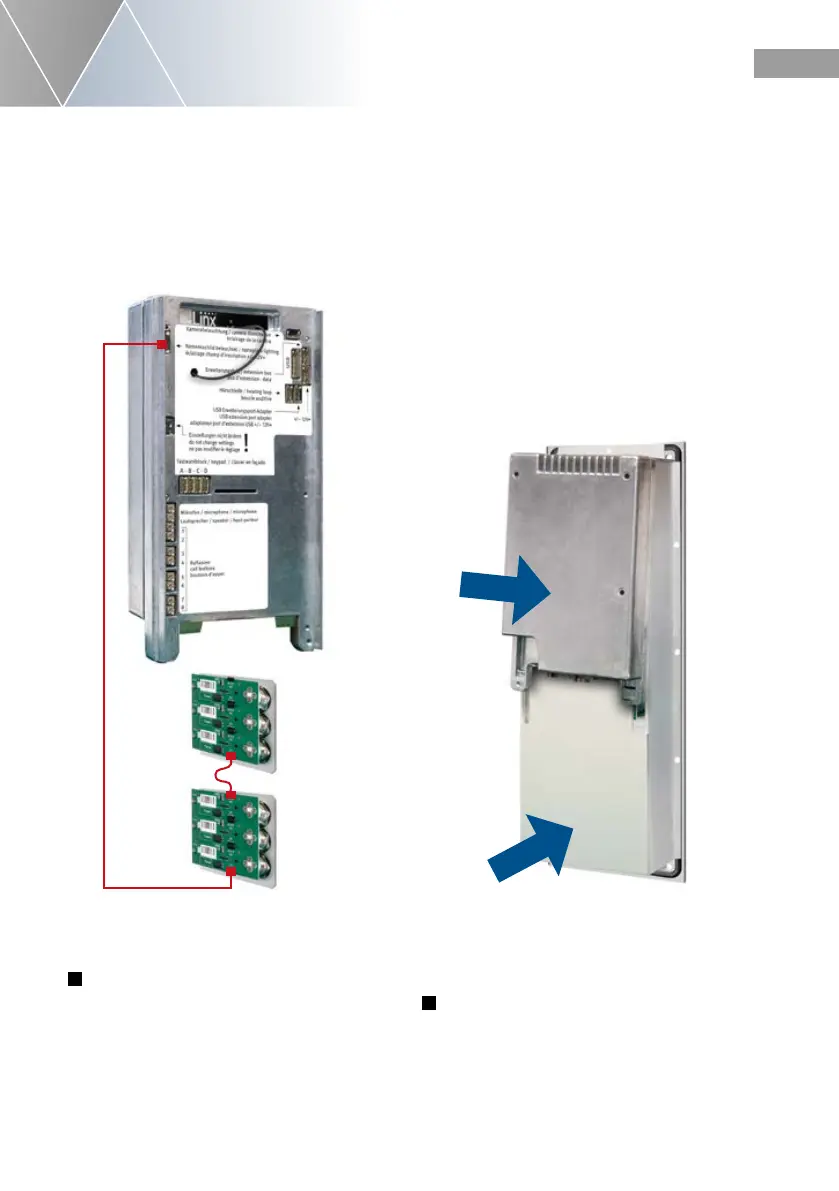
Optional: If more than one module with buttons
and nameplate or just with buttons is used, the
module panels are connected to each other as
shown in the sketch below.
“Click”
5
Place the electronics box on its front frame
incl. the screwed module housing.
First put the module housing cover and then the
electronics box back onto the module housing.
Connecting cable*
 Loading...