62 www.behnke-online.de
GB
Instructions SIP intercoms series 20-0001BS, 20-0014BS, 20-0016BS
Mounting
RT 1
RT 4
RT 5-6
RT 7-8
MIC
LP
+/- 12 V= for
Labeling
fields
RT 2
RT 3
4
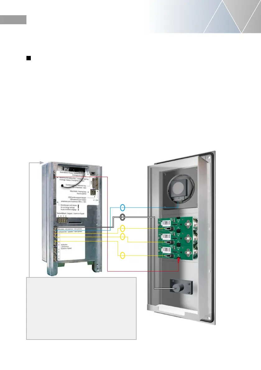
Connect the connection components of your
intercom station with your basic electronics.
Connect your connection components such as
loudspeaker, microphone, keys, keypad and
nameplates to the basic electronics as shown
as follows. For connecting an IP camera or USB
camera, refer to the instructions of the corre-
sponding products.
For example: Connecting loudspeaker,
microphone and 3 call buttons with their basic
electronics
Pin assignment of the connection cable
Series 20, 40 and 50
LP (Blue)
▸
Loudspeaker
Mic (White)
▸
Microphone
T (Yellow)
▸
Key 1 to 8 (plug contact,
Illumination board labelled
with „button“)
A/B/C/D
▸
keypad
HPI Contact
▸
Lighting 12 V=
(White) Illumination labeling field
of the and keys, see also
page 63.
In the case of basic electronics 20-0016-BS,
you will find a mounting bracket in this area for
mounting on on-site mounting points.
You can find the dimensions here:
www.behnke-online.de/masszeichungen
During installation, make sure that the intercom
station is mounted in a moisture-protected area.
 Loading...