TEMPTRONlC
CORPOPATIGN
Rev.
B:
04/15/98
TP04 100A
Operator's
Manual
2.
POWER
ON AND
OFF
2.1.
Local Operation
This manual contains instructions for local operation from the front panel of the Model
TP04100A Themostream System. Remote system operation is discussed in the
TP04100A
Interface
&
Applications Manual.
It is advisable to gain familiarity with front panel operation
before attempting remote operation.
2.2.
Main
Power
Switch
MAIN POWER SWITCH
-\
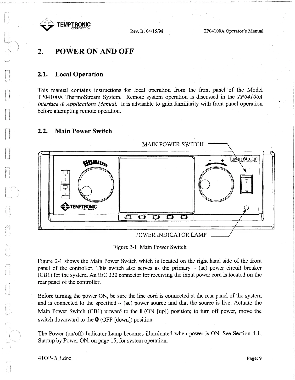
Figure 2-1 Main Power Switch
Figure
2-1 shows the Main Power Switch which is located on the right hand side of the front
panel of the controller. This switch also serves as the primary
-
(ac) power circuit breaker
(CB1) for
the
system. An IEC
320
connector for receiving the input power cord is located on the
rear panel of the controller.
Before turning the power ON, be sure the line cord is connected at the rear panel of the system
and is connected to the specified
-
(ac) power source and that the source is live. Actuate the
Main Power Switch (CBl) upward to the
I
(ON [up]) position; to turn off power, move the
switch downward to the
0
(OFF [down]) position.
The Power (onloff) Indicator Lamp becomes illuminated when power is
ON.
See Section 4.1,
Startup by Power ON, on page 15, for system operation.
41 0P-B-idoc
Page:
9
Artisan Technology Group - Quality Instrumentation ... Guaranteed | (888) 88-SOURCE | www.artisantg.com
 Loading...