www.ti.com
Connectors
5
SLUUC57A–October 2019–Revised June 2020
Submit Documentation Feedback
Copyright © 2019–2020, Texas Instruments Incorporated
BQ79600-Q1 Evaluation Module
Table 2. Jumper Placements (continued)
Pinheader Contacts Jumper Connection Populated by Default?
J10 1-2, 2-3 nUART_SPIRDY pullup to VIO
for SPI (1-2), or pulldown to
GND for UART (2-3)
Yes (2-3)
J11 1-2, 2-3 nCS pullup to VIO for SPI (1-
2), or pulldown to GND for
UART (2-3)
Yes (2-3)
J12 1-2, 2-3 SCLK pullup to VIO (1-2) or
pulldown to GND for SPI/UART
(2-3)
Yes (2-3)
J13 1-2 NFAULT pullup to VIO Yes
3.1.2 Power Supply
The power supply connection is made from either the 5-V test point or 12-V test point. When powering the
EVM directly through the 12-V battery, configure jumpers J1 and J3 in the "12V" configuration and connect
the 12-V battery to the 12-V test point. If the EVM is powered up through a PMIC or 5-V regulator,
configure jumpers J1 and J3 in the "5V" configuration and connect the PMIC/regulator 5-V output to the 5-
V test point.
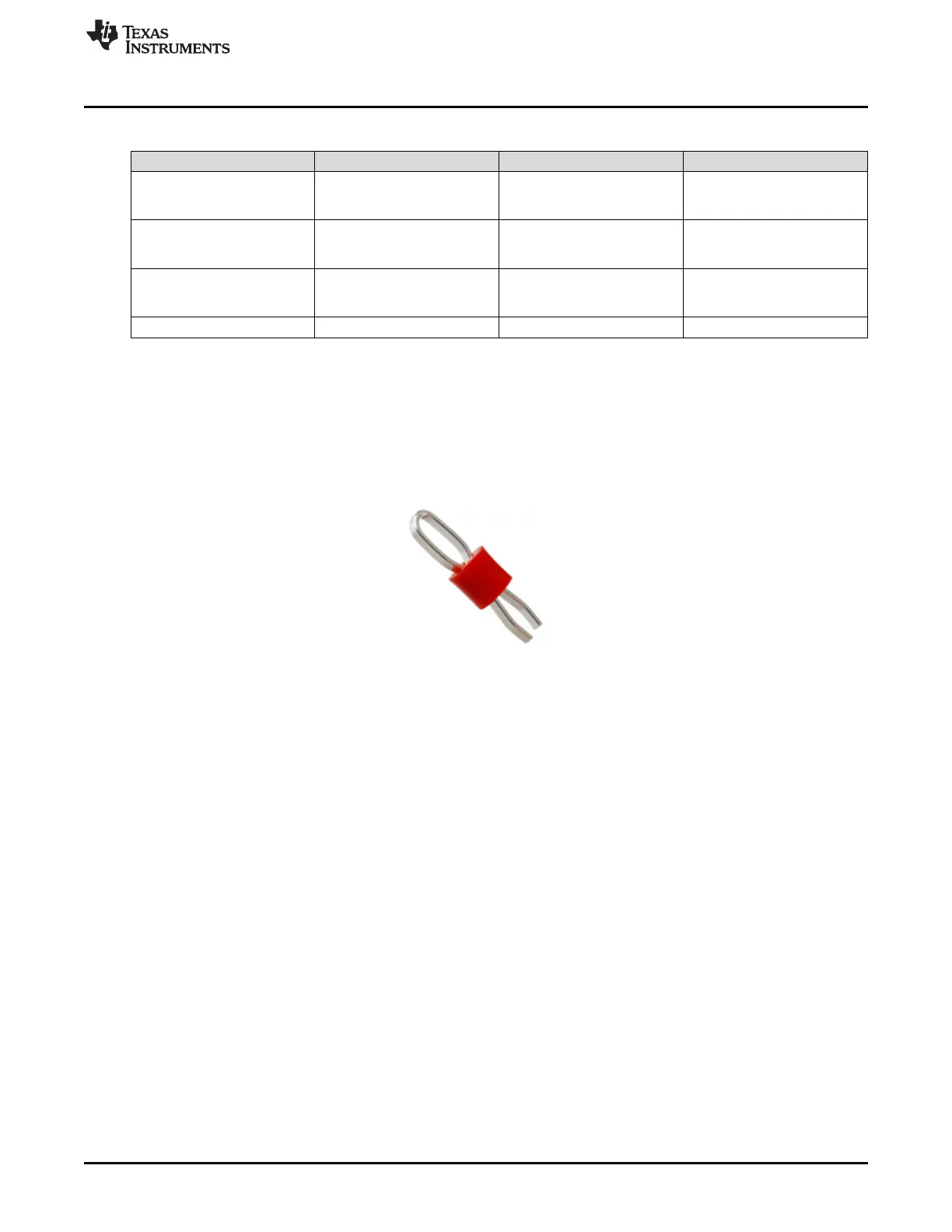
Figure 2. Keystone5010 (reference image only)

 Loading...


