www.ti.com
Connectors
7
SLUUC57A–October 2019–Revised June 2020
Submit Documentation Feedback
Copyright © 2019–2020, Texas Instruments Incorporated
BQ79600-Q1 Evaluation Module
Table 5. Pin Description
Pin Name
1 NC
2 nUART/SPI (SPI_RDY) signal from BQ79600-Q1
3 USB2ANY SCLK (SCLK of BQ79600-Q1)
4 nFAULT signal from BQ79600-Q1
5 GND
6 USB2ANY 3.3 V
7 USB2ANY TX ( MOSI_RX of BQ79600-Q1 )
8 USB2ANY RX ( MISO_TX of BQ79600-Q1 )
9 USB2ANY CS (nCS of BQ79600-Q1)
10 NC
The 6-pin J2 - serial connector is used to connect the BQ79600EVM to a PC running the GUI or to a host
controller through a TTL-232R-5V FTTI cable. Only UART is supported.
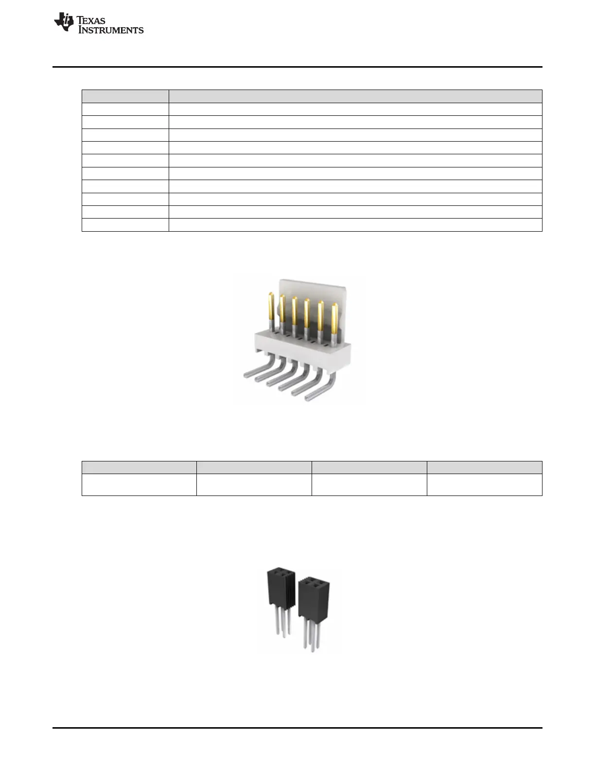
Figure 4. Molex 0022124062 (reference image only)
Table 6. Connector Information
Designator Manufacturer Part Number Mating Connector
J2 Molex Manufacturer: 0022124062 6-pin connector in TTL-232R-
5V FTTI cable
The 20-pin J7 - serial connector and the 20-pin J9-serial connector are used to connect the BQ79600EVM
to a host controller. The BoosterPack in the LAUNCHXL2-TMS57012 LaunchPad™ can be directly
plugged into the J7 and J9 connectors. Before making the connections between the EVM and the
LaunchPad™, follow the steps described in Section 4.3 to ensure the boards are configured correctly.
Figure 5. Samtec SSQ-110-03-T-D (reference image only)

 Loading...


