Hardware
www.ti.com
10
SLAU597E–March 2015–Revised January 2018
Submit Documentation Feedback
Copyright © 2015–2018, Texas Instruments Incorporated
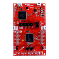
MSP432P401R SimpleLink™ Microcontroller LaunchPad™ Development Kit
(MSP
‑
EXP432P401R)
2.3.3 Using an External Debug Probe Instead of the Onboard XDS110-ET
Many users have a specific external debug probe that they prefer to use, and may wish to bypass the
XDS110-ET debug probe to program the MSP432 target MCU. This is enabled by jumpers on isolation
block J101, and the connector J8. Using an external debug probe is simple, and full JTAG access is
provided through J8.
1. Remove jumpers on the JTAG signals on the J101 isolation block, including RST, TMS, TCK, TDO,
and TDI.
2. Plug any ARM debug probe into J8.
a. J8 follows the ARM Cortex Debug Connector standard outlined in Cortex-M Debug Connectors.
3. Plug USB power into the LaunchPad development kit, or power it externally.
a. Ensure that the jumpers across 3V3 and GND are connected if using USB power.
b. External debug probes do not provide power, the VCC pin is a power sense pin.
c. For more details on powering the LaunchPad development kit, see Section 2.4.
2.3.4 Using the XDS110-ET Debug Probe With a Different Target
The XDS110-ET debug probe on the LaunchPad development kit can interface to most ARM Cortex-M
devices, not just the onboard target MSP432P410R device. This functionality is enabled by the J102 10-
pin Cortex-M JTAG connector. The 10-pin cable can be purchased from Digi-Key Electronics (sold
separately from the LaunchPad development kit).
Header J102 follows the Cortex-M ARM standard; however, pin 1 is not a voltage sense pin. The XDS110-
ET outputs only 3.3-V JTAG signals. If another voltage level is needed, the user must provide level
shifters to translate the JTAG signal voltages. Additionally, 3.3 V of output power can be sourced from the
XDS110-ET when jumper JP102 is connected. This allows the XDS110-ET to power the external target at
3.3 V through pin 1. By default JP102 is not populated as it does not explicitly follow the standard.
1. Remove jumpers on the JTAG signals on the J101 isolation block, including RST, TMS, TCK, TDO,
and TDI.
2. Plug the 10-pin cable into J102, and connect to an external target.
a. J102 follows the ARM Cortex Debug Connector standard outlined in Cortex-M Debug Connectors.
3. Plug USB power into the LaunchPad development kit, or power it externally
a. JTAG levels are 3.3 V ONLY.
b. 3.3-V power can be sourced through J102 by shorting the JP102 jumper.
2.3.5 EnergyTrace+ Technology
EnergyTrace™ technology is an energy-based code analysis tool that measures and displays the
application's energy profile and helps to optimize it for ultra-low power consumption.
MSP432 devices with built-in EnergyTrace+[CPU State] (or in short EnergyTrace+) technology allow real-
time monitoring of internal device states while user program code executes.
EnergyTrace+ technology is supported on the LaunchPad development kit MSP432P401R device +
XDS110-ET debug probe. EnergyTrace technology is available as part of TI's Code Composer Studio IDE.
During application debug, additional windows are available for EnergyTrace technology.
To enable EnergyTrace technology, go to:
• Window > Preferences > Code Composer Studio > Advanced Tools > EnergyTrace™ Technology
• Check the Enable Auto-Launch on target connect box