Software Examples
www.ti.com
24
SLAU597E–March 2015–Revised January 2018
Submit Documentation Feedback
Copyright © 2015–2018, Texas Instruments Incorporated
MSP432P401R SimpleLink™ Microcontroller LaunchPad™ Development Kit
(MSP
‑
EXP432P401R)
3.3 430BOOST-SHARP96 Graphics Library Example
This software example is similar to the BOOSTXL-K350QVG-S1 Graphics library example. It shows how
to use the MSP Graphics Library, or "grlib," in a project with the Sharp 96×96 display. The Sharp 96×96
display BoosterPack plug-in module does not support touch or color, it is a simple monochrome LCD. It is
a great LCD for ultra-low power display applications and has a unique mirrored pixel display.
This demo cycles screens without user interaction to show simple graphics primitives.
• Pixels
• Lines
• Circles
• Rectangles
• Text
• Images
This demo introduces the functions to configure grlib such as initialization, color inversion, and using
foreground and background colors properly.
3.4 BOOSTXL-BATPAKMKII_FuelGauge_MSP432P401R
This section describes the functionality and structure of the BOOSTXL-
BATPAKMKII_FuelGauge_MSP432P401R demo that is included in the SimpleLink MSP432 SDK (see
Section 4.3).
3.4.1 Source File Structure
The project is split into multiple files (see Table 6). This makes it easier to navigate and reuse parts of it
for other projects.
Table 6. Source File and Folders
Name Description
Library: driverlib Device driver library (MSP432DRIVERLIB)
startup_msp432p401r.c MSP432™ MCU family interrupt vector table for CGT
HAL_BQ27441.c Driver for communicating with the bq27441-G1 fuel gauge
HAL_I2C.c Board specific support driver for I
2
C communication
HAL_UART.c Board specific driver for UART communication through Application/User UART
main.c The main function of the demo, global variables, and more
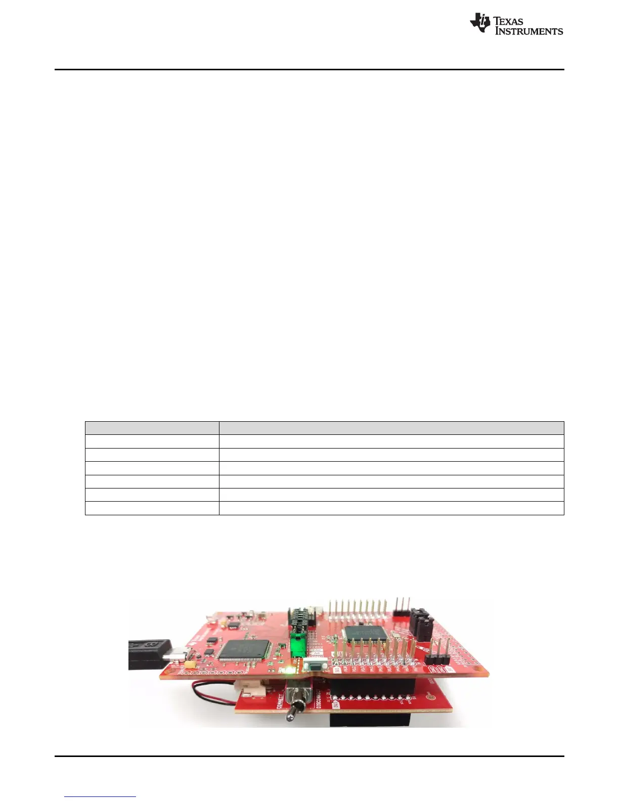
3.4.2 Running the Fuel Gauge Example
After the compiling and loading the BOOSTXL-BATPAKMKII_FuelGauge_MSP432P401R project or
downloading the prebuilt firmware binary onto the MSP-EXP432P401R LaunchPad development kit, follow
the steps below to run the demo firmware.
Figure 17. Hardware Setup and Connections
 Loading...