www.ti.com
Hardware
11
SPRUIM4B–December 2018–Revised May 2020
Submit Documentation Feedback
Copyright © 2018–2020, Texas Instruments Incorporated
xWR1843 Evaluation Module (xWR1843BOOST) Single-Chip mmWave
Sensing Solution
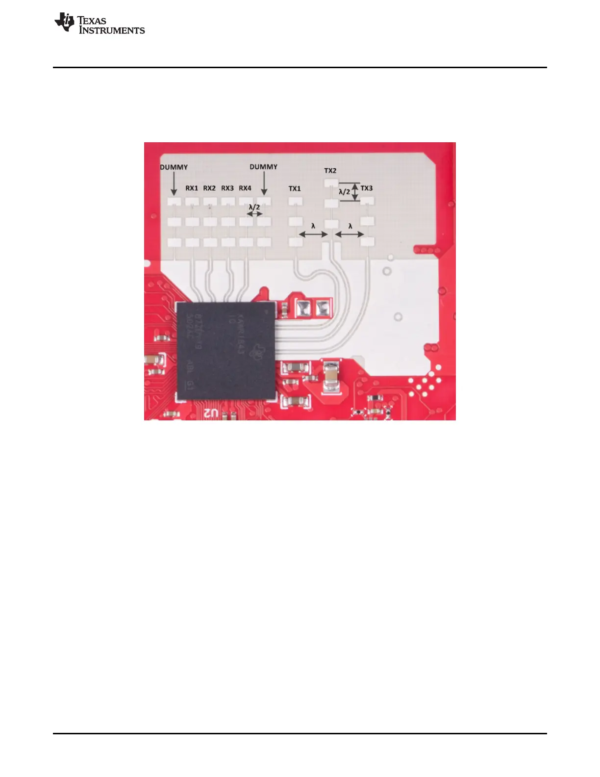
2.7 Antenna
The BoosterPack includes onboard-etched antennas for the four receivers and three transmitters that
enable tracking multiple objects with their distance and angle information. This antenna design enables
estimation of distance and elevation angle that enables object detection in a three-dimensional plane.
Figure 10 shows the PCB antennas.
Figure 10. RX and TX Antennas
The antenna peak gain is > 10.5 dBi across the frequency band of 76 to 81 GHz. The radiation pattern of
the antenna in the horizontal plane (H-plane) and elevation plane (E-plane) is as shown in Figure 11 and
Figure 12.
The beamwidth of the antenna design can be determined from the radiation patterns. For example, at 78
GHz, based on 3-dB drop in the gain as compared to bore sight, the horizontal 3dB-beamwidth is
approximately ±28 degrees (see Figure 11), and elevation 3dB-beamwidth is approximately ±14 degrees
(see Figure 12). Similarly, the horizontal 6dB-beamwidth is approximately ±50 degrees (see Figure 11)
and the elevation 6dB-beamwidth is approximately ±20 degrees (see Figure 12).

 Loading...


