www.ti.com
Hardware
5
SPRUIM4B–December 2018–Revised May 2020
Submit Documentation Feedback
Copyright © 2018–2020, Texas Instruments Incorporated
xWR1843 Evaluation Module (xWR1843BOOST) Single-Chip mmWave
Sensing Solution
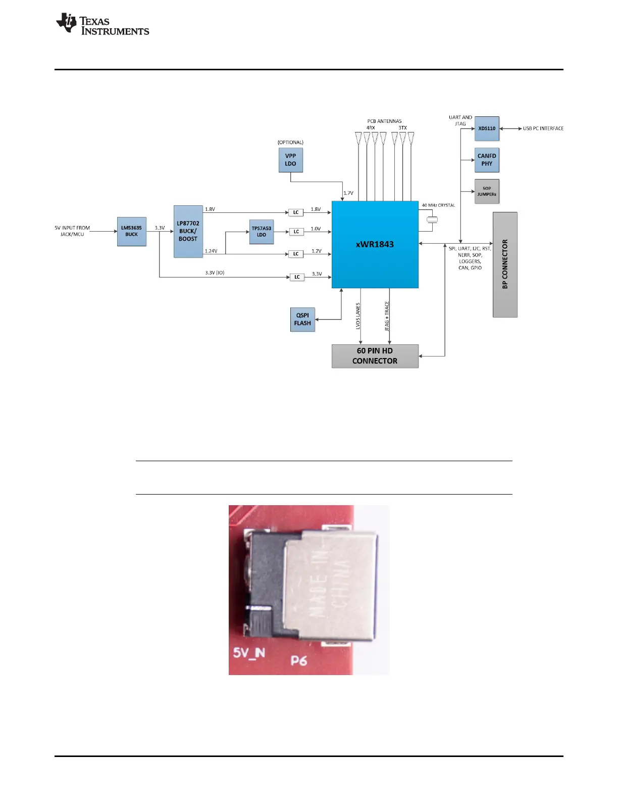
2.1 Block Diagram
Figure 3 shows the block diagram.
Figure 3. Block Diagram
2.2 Power Connections
The BoosterPack is powered by the 5-V power jack (2.5-A current limit), shown in Figure 4. As soon as
the power is provided, the NRST and 5-V LEDs should glow, indicating that the board is powered on.
NOTE: After the 5-V power supply is provided to the EVM, it is recommended to press the NRST
switch (SW2) one time to ensure a reliable boot-up state.
Figure 4. Power Connector

 Loading...


